Illumination system and method for recycling light to increase the brightness of the light source

a technology of illumination system and light source, which is applied in the direction of instruments, lighting and heating apparatus, fibre light guides, etc., can solve the problems of not being able to achieve low cost applications using small imaging panels or with larger screens, and not being able to achieve the desired brightness of leds. , to achieve the effect of enhancing the recycling effect of recycling devices, and increasing the brightness of light sources

Active Publication Date: 2007-12-20
MEADOWSTAR ENTERPRISES
View PDF19 Cites 117 Cited by
  • Summary
  • Abstract
  • Description
  • Claims
  • Application Information

AI Technical Summary

Benefits of technology

[0008] Another object of the present invention is to provide the illumination system comprising a recycling device to recycle a portion of the light emitted by the light source to increase the brightness of the light output.
[0020] In accordance with an exemplary embodiment of the present invention, a method for increasing the brightness of a light source, comprises the steps of: coupling an optical recycling device to a light source to receive a plurality of rays of light from the light source; recycling a portion of the plurality of rays of light back to the light source; and re-emitting the portion of the plurality of rays of light to the optical recycling device by the light source, thereby increasing the brightness of the light source's output.

Problems solved by technology

However, this can be both technologically impossible if there is a limited space for integrating light sources and economically unfeasible as it can be expensive to integrate and use multiple light sources.
Although this light source is the brightest at the lowest cost, the need to split the white light into 3 colors and the short lifetime make is less desirable.
However, at the present time, LEDs are not bright enough for low cost application using small imaging panels or with larger screens.
Unfortunately, the currently available LEDs are not bright enough to be useful in illuminating large projection television screens, which are increasingly popular with the consumer.

Method used


Image

  • Illumination system and method for recycling light to increase the brightness of the light source
  • Illumination system and method for recycling light to increase the brightness of the light source
  • Illumination system and method for recycling light to increase the brightness of the light source

Examples


Embodiment Construction

[0050] With reference to the figures, exemplary embodiments of the invention are now described. These embodiments illustrate principles of the invention and should not be construed as limiting the scope of the invention.

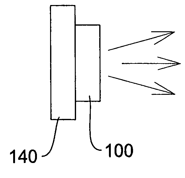
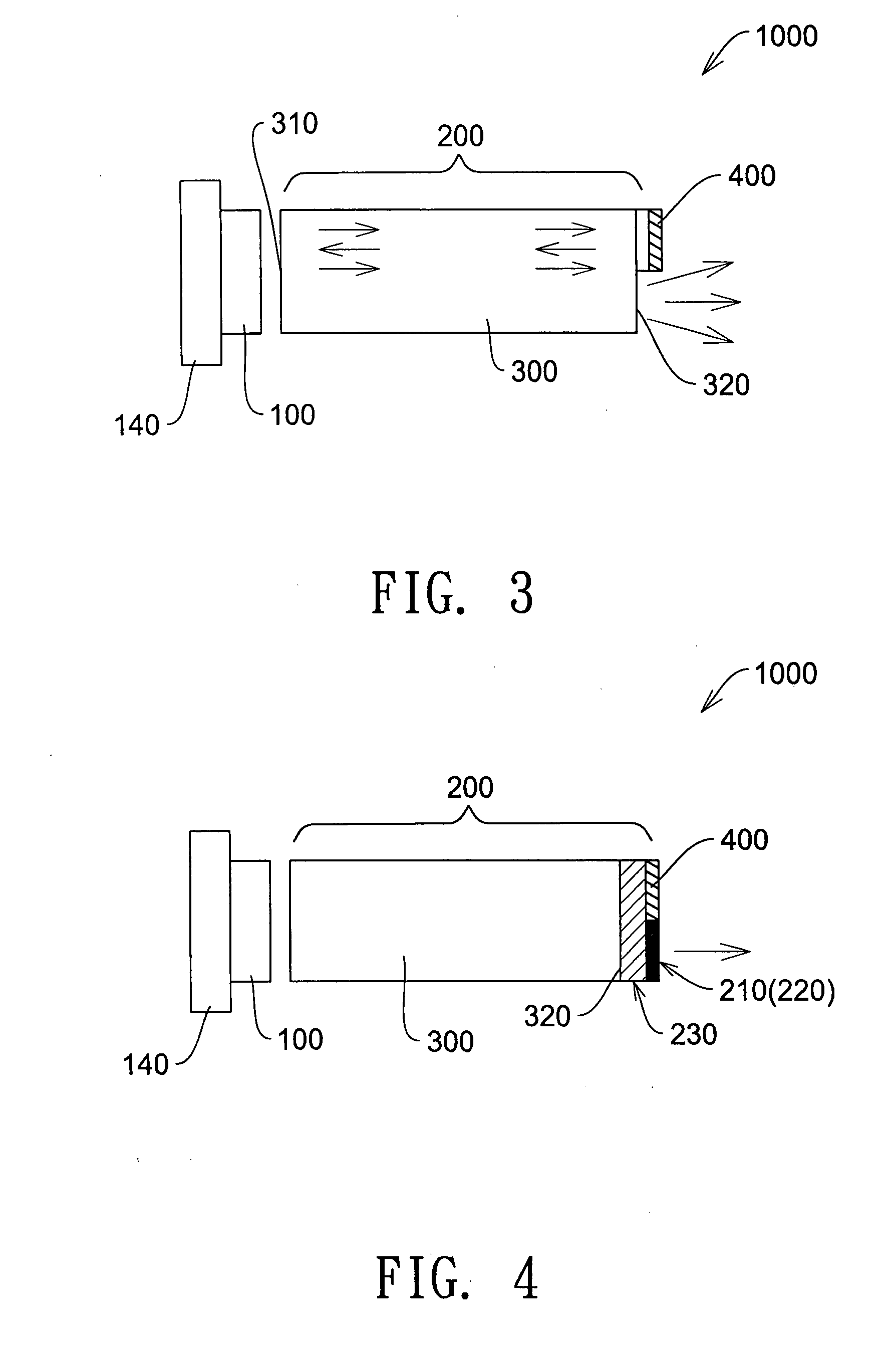
[0051] In accordance with exemplary embodiments of the present invention, as shown in FIGS. 3-5, 7-18, the illumination system 1000 for recycling light to increase the brightness of the light source comprises a light source 100 and an optical recycling device 200. As shown in FIG. 1, the light source 100 is mounted on a substrate 140. The substrate 140 is preferably though not limited to a heatsink 140 for absorbing and dissipating heat emitted from light source 100. Light source 100 is preferably a light emitting diode (“LED”). The LED or light source 100 can be mounted to the substrate 140 as a bare chip, a chip with a protective coating, or a chip with a lens or collimating lens mounted thereon. The chip size can be as small as less than 1 mm by 1 mm, or as large...


PUM

PropertyMeasurementUnit
sizeaaaaaaaaaa
reflectivityaaaaaaaaaa

Abstract

An illumination system for increasing the brightness of a light source comprises an optical recycling device coupled to the light source, preferably light emitting diode (LED), for spatially and / or angularly recycling light. The optical recycling device spatially recycles a portion of rays of light emitted by the LED back to the light source using a reflector or mirror and / or angularly recycles high angle rays of light and transmits small angle rays of light, thereby increasing the brightness of the light source's output.

Description

CROSS-REFERENCE TO RELATED APPLICATIONS [0001] This application claims the benefit of U.S. Provisional Application Ser. No. 60 / 813,186, filed Jun. 13, 2006, U.S. Provisional Application Ser. No. 60 / 814,605, filed Jun. 16, 2006, U.S. Provisional Application Ser. No. 60 / 830,946, filed Jul. 13, 2006, U.S. Provisional Application Ser. No. 60 / 842,324, filed Sep. 5, 2006, U.S. Provisional Application Ser. No. 60 / 848,429, filed Sep. 28, 2006, and U.S. Provisional Application Ser. No. 60 / 855,330, filed Oct. 30, 2006, each of which is incorporated herein by reference in its entirety.BACKGROUND [0002] This invention relates to systems and methods for increasing the brightness of illumination systems, particularly for an illumination system and method that recycles light emitted from a light source in order to increase the brightness of that light source. [0003] Light sources are used in all types of illumination applications. Typical light sources include but are not limited to arc lamps, hal...

Claims


Application Information

Patent Timeline
Patent Type & Authority Applications(United States)
IPC IPC(8): F21V7/00
CPCF21K9/00G02B6/0008G02B27/0994Y10T29/49826G03B33/06G03B33/12Y10S362/80G03B21/14F21V7/041F21V7/043F21V9/14G02B6/00G03B21/208G03B21/2033F21K9/61F21V7/00
Inventor LI, KENNETH K.INATSUGU, SEIJI
Owner MEADOWSTAR ENTERPRISES
Why Eureka
Try Eureka