
Recording method and optical disk recording device

a recording device and optical disc technology, applied in the direction of overwriting/replacing recorded data, digital signal error detection/correction, instruments, etc., can solve the problem that the processing operation cannot be completed under the normal condition, and achieve the effect of high speed

Inactive Publication Date: 2007-12-20
HITACHI CONSUMER ELECTRONICS CORP +1
View PDF6 Cites 7 Cited by
  • Summary
  • Abstract
  • Description
  • Claims
  • Application Information

AI Technical Summary

Benefits of technology

The patent text describes a method for managing recorded areas on a write-once optical disc, such as a DVD-R, using a linear replacement process. The method allows for recovery of data if there are unexpected defects in the disc. The text also describes a method for managing file systems on the optical disc using the UDF format, which includes a meta data file for managing file management information. The technical effects of the patent text include improved reliability of the optical disc and better management of recorded data on the disc.

Problems solved by technology

Normally, although these process operations are accomplished under normal condition, there are some possibilities that the process operations cannot be completed under the normal condition due to a very few number of unexpectable reasons.
For instance, in such a case that an optical disc contains a defect within a user area, and the DVD-RAM drive fails in recording of user data with respect to a recording command, the DVD-RAM drive performs such an error recovery process operation as a retry process operation and a linear replacement process operation.

Method used


Image

  • Recording method and optical disk recording device
  • Recording method and optical disk recording device
  • Recording method and optical disk recording device

Examples


Embodiment Construction

[0043]It should be understood that although various embodiments as to recording methods according to the present invention will be described in detail with reference to drawings, the present invention is not limited only to the below-mentioned embodiment modes.

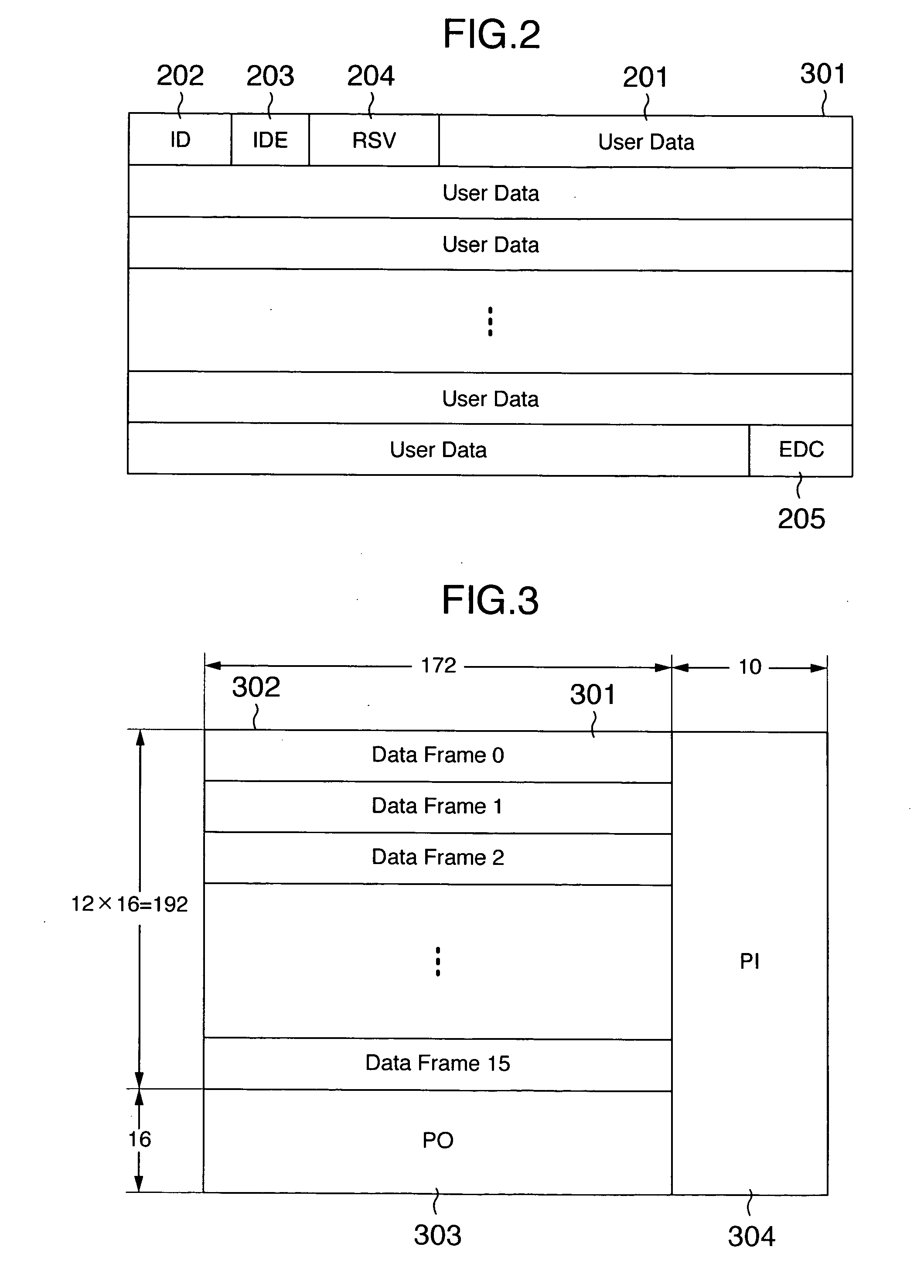
[0044]In the beginning, a description is made of basic structures as to formats of recording data and drives, which are used in explanations of the present invention with reference to FIG. 2 to FIG. 4.

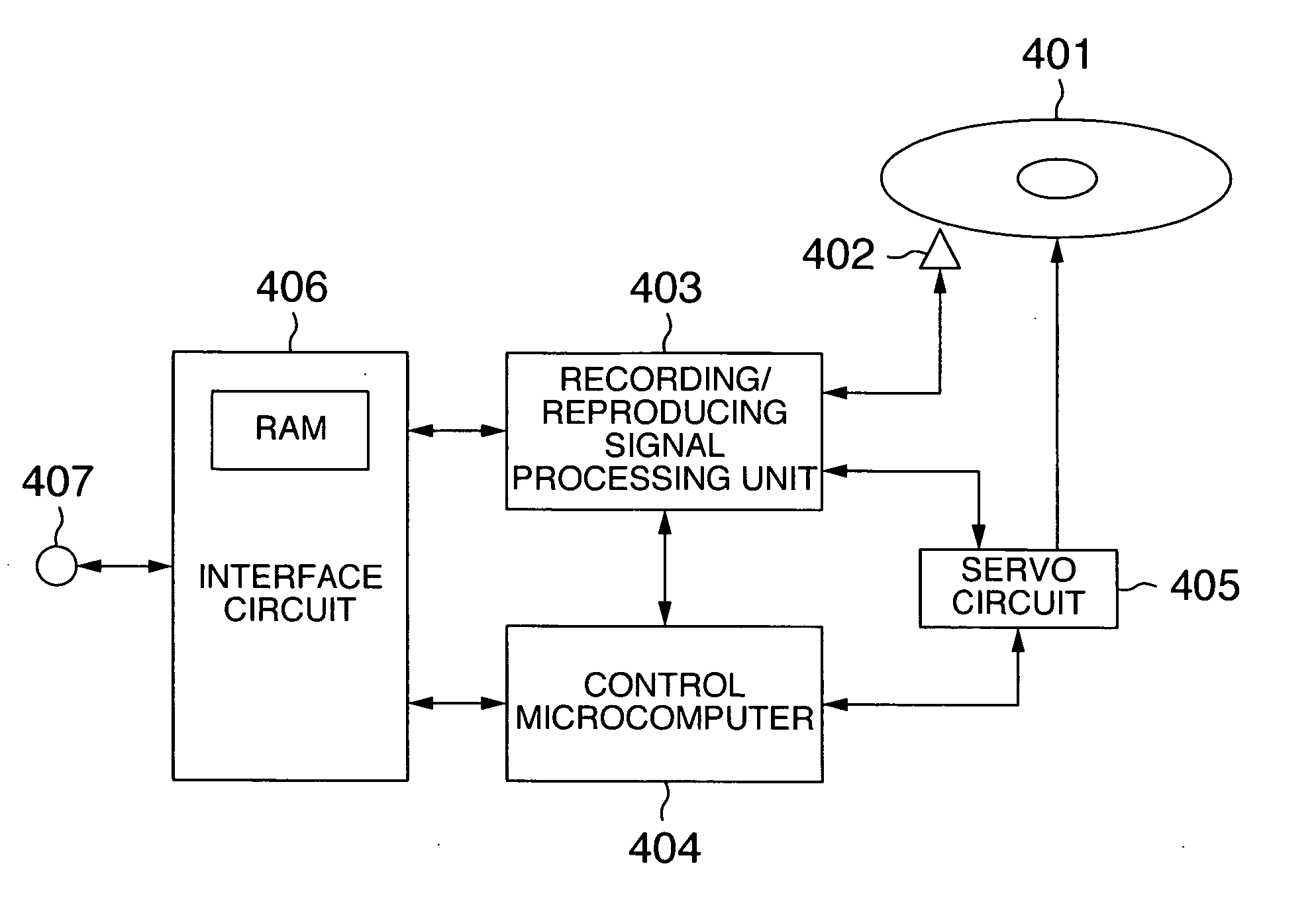
[0045]FIG. 4 indicates an example as to an arrangement of an optical disc drive according to an embodiment of the present invention. As shown in FIG. 4, the optical disc drive is equipped with an optical head 402, a recording / reproducing signal processing circuit 403, a control microcomputer 404, a servo circuit 405, an interface circuit 406, an input / output terminal 407. The optical head 402 mounts thereon a laser diode and a photodetector. The recording / reproducing signal processing circuit 403 performs an encoding process oper...


PUM

PropertyMeasurementUnit
areaaaaaaaaaaa
recordable areasaaaaaaaaaa
areasaaaaaaaaaa

Abstract

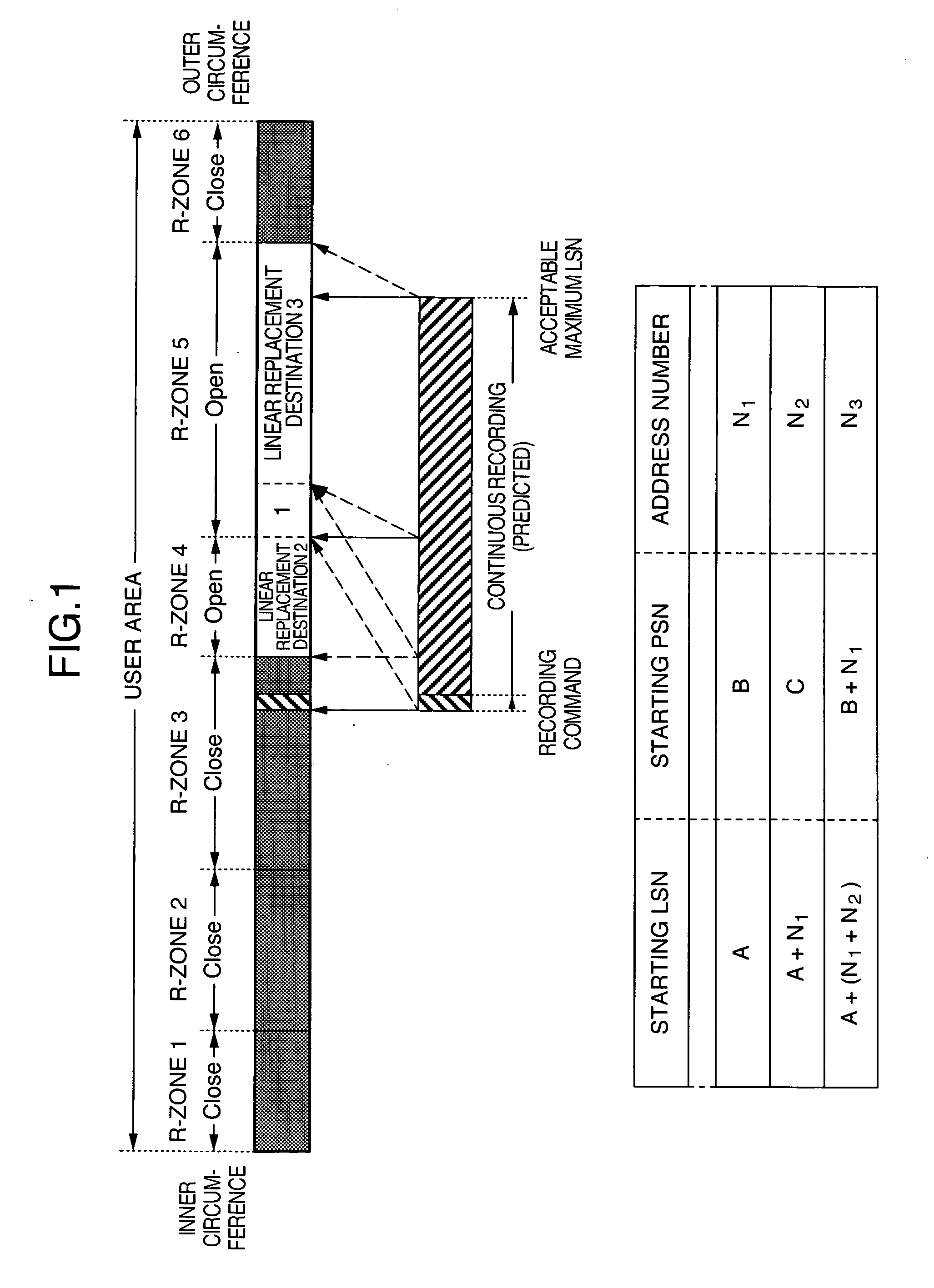
A recording method and a recording apparatus capable of optimally arranging data on a write-once type optical disc. In a write-once type optical disc recording method with respect to a disc having a read-in, a user area, and a read-out by employing defect management information, the user area is divided into 3, or more pieces of R-zones; at least 2 recordable R-zones having recordable areas are present. When an unrecordable R-zone having no recordable area is present on the read-in side rather than two, or more pieces of the R-zones among the R-zones having the recordable areas, a linear replacement destination of a logical overwriting is determined to such an R-zone other than an R-zone having a recordable area, which is located adjacent to the unrecordable R-zone.

Description

INCORPORATION BY REFERENCE[0001]The present application claims priority from Japanese application JP2006-164172 filed on Jun. 14, 2006, the content of which is hereby incorporated by reference into this application.BACKGROUND OF THE INVENTION[0002]1. Field of the Invention[0003]The present invention generally relates to a recording method of an optical disc, and a recording apparatus of an optical disc. More specifically, the present invention is directed to a recording method and a recording apparatus, which are employed so as to record digital data on a write-once type optical disc.[0004]As one example of apparatuses for recording and / or reproducing digital data on / from recording media, there are recording / reproducing apparatuses (drives) of DVD-RAMs which have been defined in “Standard ECMA-272: 120 mm DVD Rewritable Disc (DVD-RAM)” ECMA 1999 (pages 43 to 55), and so on.[0005]When a DVD-RAM disc is inserted into this DVD-RAM drive, or a power supply thereof is turned ON, the DVD-...

Claims


Application Information

Patent Timeline
Patent Type & Authority Applications(United States)
IPC IPC(8): G11B20/10
CPCG11B20/10G11B20/1883G11B27/326G11B2020/10907G11B2020/1235G11B2220/2575G11B2020/1278G11B2020/1826G11B2220/20G11B2220/218G11B2220/2562G11B2020/1267
Inventor HOSHIZAWA, TAKUFUCHIWAKI, ATSUSHI
Owner HITACHI CONSUMER ELECTRONICS CORP
Learn More