Techniques for wireless deployment

Inactive Publication Date: 2007-12-20
IBAHN GEN HLDG
View PDF5 Cites 28 Cited by
  • Summary
  • Abstract
  • Description
  • Claims
  • Application Information

AI Technical Summary

Benefits of technology

[0017]According to yet a further specific embodiment, a wireless network is provided which includes a plurality of access devices for enabling wireless access to the network by a plurality of client devices. First ones of the access devices are configured to transmit signals having a first polarization. Second ones of the access devices are configured to transmit signals having a second polarization different from the first. The first and second access devices

Problems solved by technology

It is often not technically feasible to “dial down” the power of a transceiver to the point where it would continue to be useful in its intended area without transmitting beyond such barriers.
In addition, reducing the transmission power of access points increases areas of shadow (or signal detected from other access points), while decreasing the ratio of signal to noise.
These are both undesirable results in that they increase the likelihood that a client device might roam to an out-of-area access point.
However, closed environments such as building interiors and dense urban areas present conditions which seriously degrade the efficacy of such techniques.
That is, the combination of reflection, refraction, multi-path, and signal absorp

Method used


Image

  • Techniques for wireless deployment
  • Techniques for wireless deployment

Examples


Example

[0020]Reference will now be made in detail to specific embodiments of the invention including the best modes contemplated by the inventors for carrying out the invention. Examples of these specific embodiments are illustrated in the accompanying drawings. While the invention is described in conjunction with these specific embodiments, it will be understood that it is not intended to limit the invention to the described embodiments. On the contrary, it is intended to cover alternatives, modifications, and equivalents as may be included within the spirit and scope of the invention as defined by the appended claims. In the following description, specific details are set forth in order to provide a thorough understanding of the present invention. The present invention may be practiced without some or all of these specific details. In addition, well-known features may not have been described in detail to avoid unnecessarily obscuring the invention.

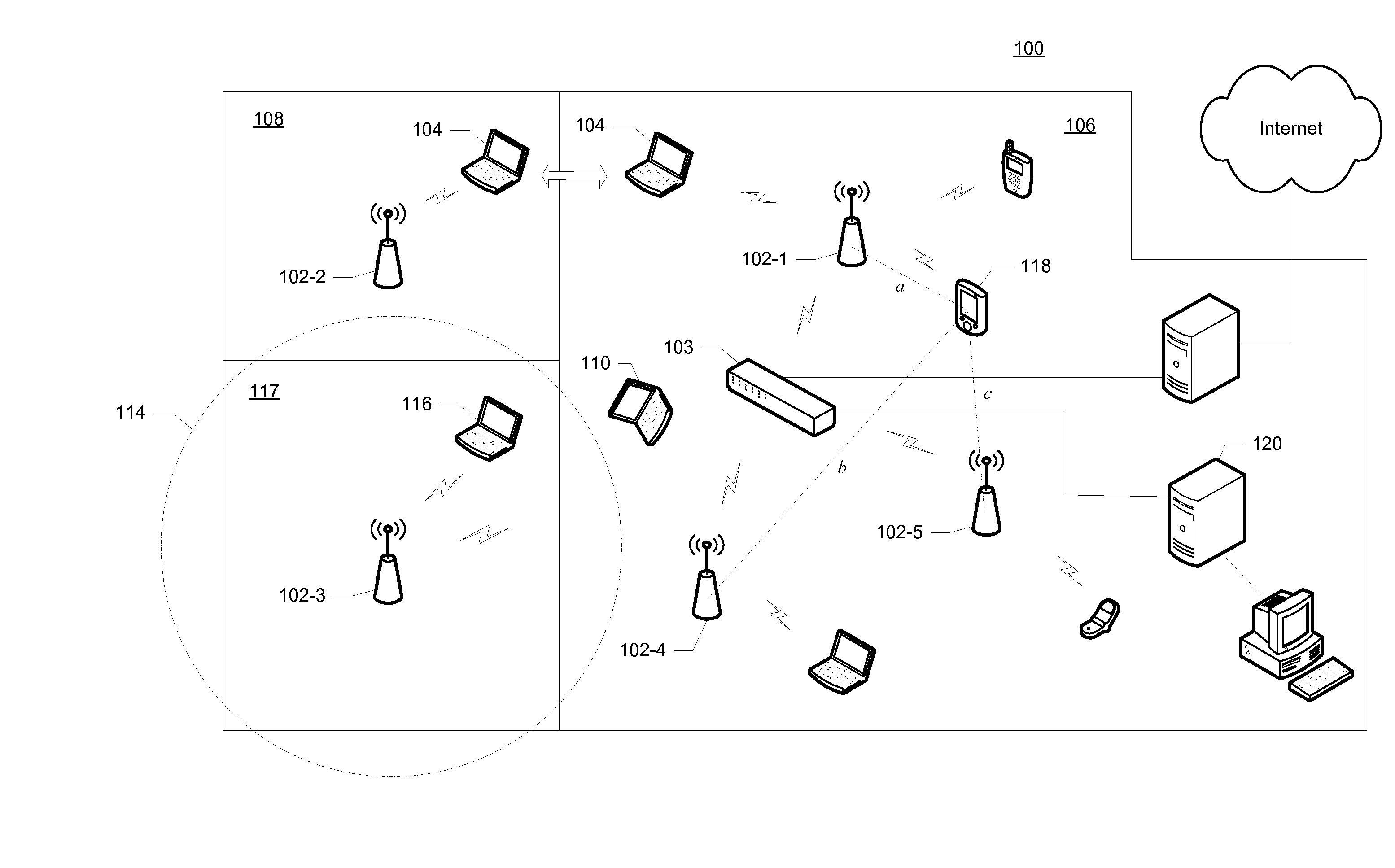
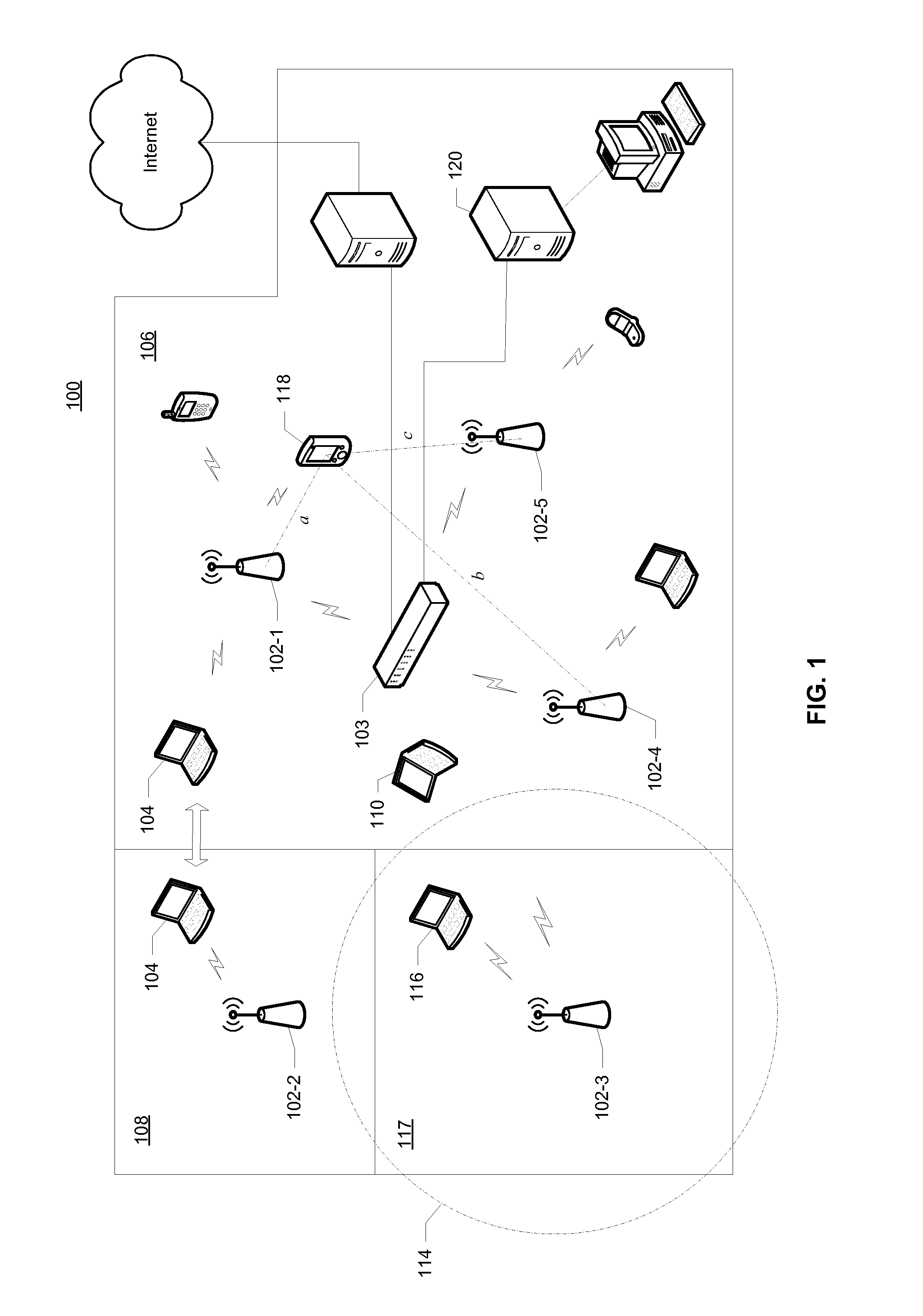
[0021]FIG. 1 is a simplified network dia...


PUM


Abstract

A variety of techniques are described in which wireless access points or base stations are deployed in wireless networks to achieve geographic isolation, i.e., distinct zones of operation having well-defined geographic boundaries, and increased overall capacity in an area having a high population of access and client devices.

Description

RELATED APPLICATION DATA[0001]The present application claims priority under 35 U.S.C. 119(e) to U.S. Provisional Patent Application No. 60 / 813,993 for TECHNIQUES FOR WIRELESS DEPLOYMENT TO MAXIMIZE CAPACITY AND GEOGRAPHIC ISOLATION filed on Jun. 14, 2006 (Attorney Docket No. STSNP009P), the entire disclosure of which is incorporated herein by reference for all purposes.BACKGROUND OF THE INVENTION[0002]The present invention relates to wireless networks and, in particular, to a variety of techniques for the deployment and operation of access points in wireless networks to improve capacity and geographic isolation.[0003]Wireless networks typically employ egress / access devices, commonly referred to as access points, which form points of presence for client radio devices. An access point may act alone in its function but is often deployed in an array or cellular structure with predictable and overlapping coverage from cell to cell. Client devices act as end-points for telemetry and data ...

Claims


Application Information

Patent Timeline
IPC IPC(8): H04Q7/24H04W48/02
CPCH04W48/02H04W88/08H04B15/00H04W16/18H04W48/20H04W48/18H04B7/10
Inventor WELCH, JOHN THOMASSMITH, GARY L.DREWS, MICHAEL DAVIDMIDANI, WAEL R.
Owner IBAHN GEN HLDG
Why Eureka
Try Eureka