Hybrid blade for a steam turbine

a steam turbine and hybrid technology, applied in the field of hybrid blades of steam turbines, can solve the problems of reducing reliability, blades contributing to higher disk stresses, and low performan

Active Publication Date: 2007-12-20
GENERAL ELECTRIC CO
View PDF11 Cites 49 Cited by
  • Summary
  • Abstract
  • Description
  • Claims
  • Application Information

AI Technical Summary

Problems solved by technology

This increasing section area of the blade at lower spans contributes to excessive flow blockage at the root and thus lower performance.
The weight of the blade contributes to higher disk stresses and thus to potentially reduced reliability.

Method used


Image

  • Hybrid blade for a steam turbine
  • Hybrid blade for a steam turbine
  • Hybrid blade for a steam turbine

Examples


Embodiment Construction

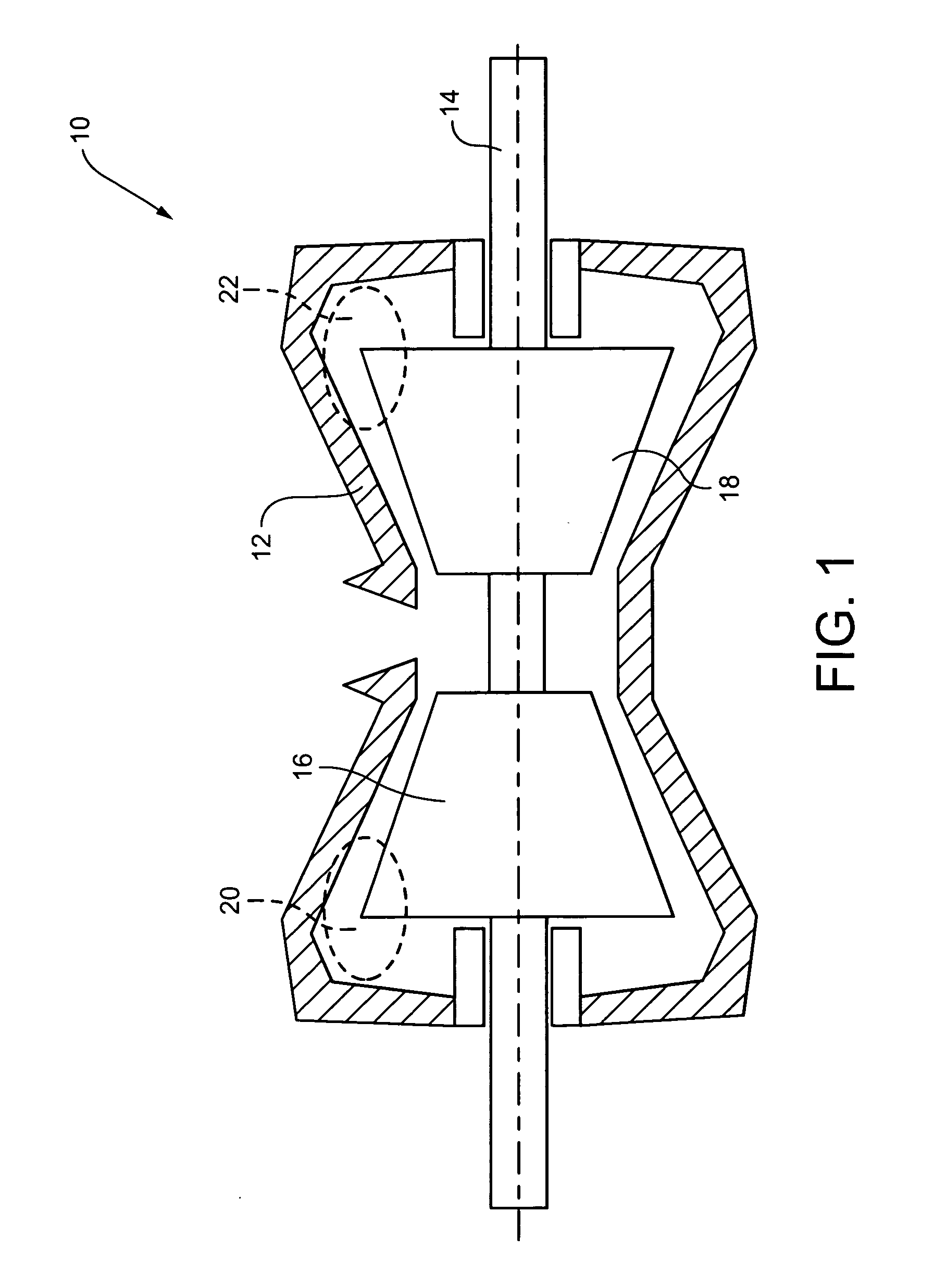
[0016]FIG. 1 is a schematic diagram of a double-flow, low pressure turbine 10 including a turbine casing 12, rotor 14 and a plurality of wheels in two turbine sections indicated at 16, 18. The areas 20, 22 circled in dotted lines represent the radially outermost regions of the last stage blades that have been shown to experience the most windage heating during partial load conditions.

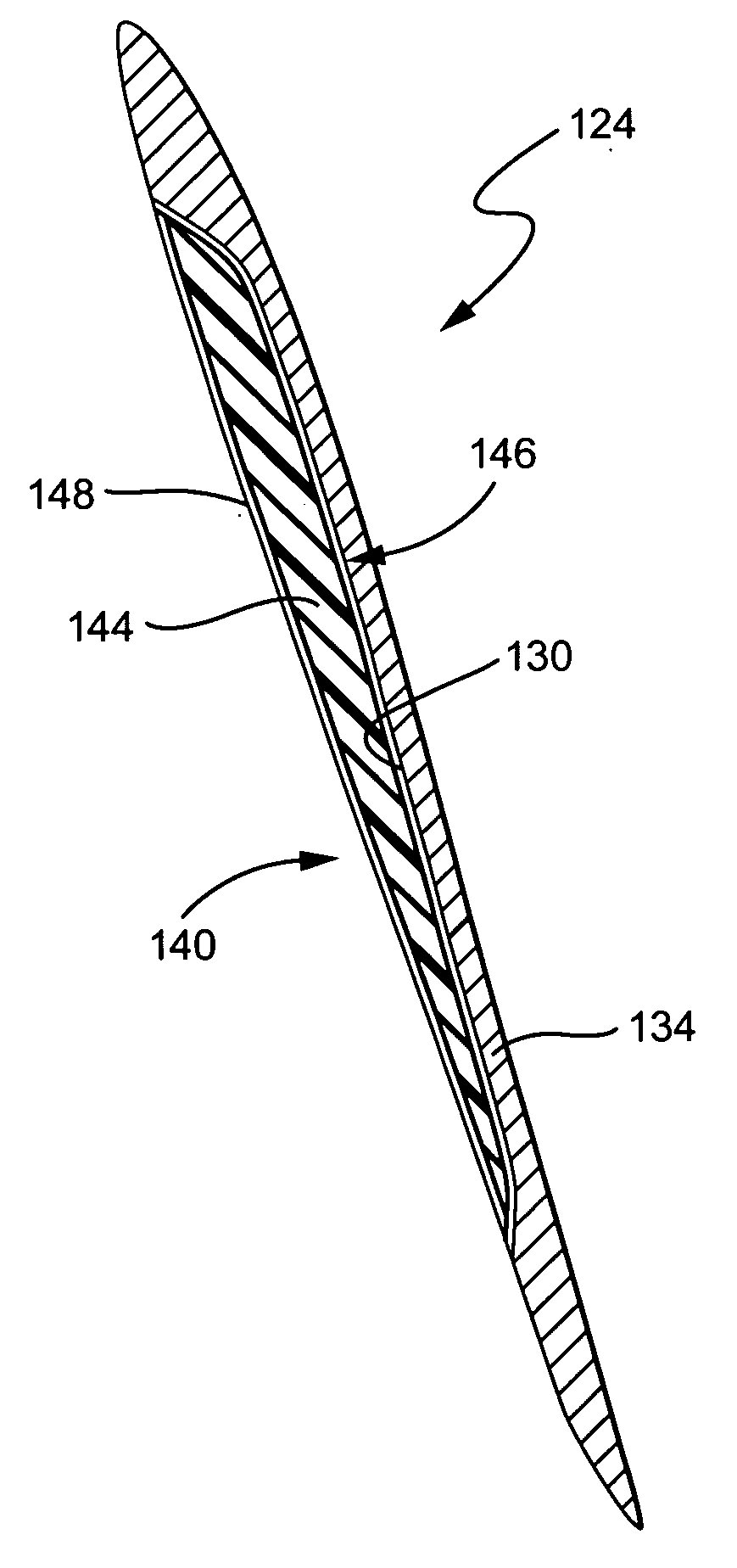
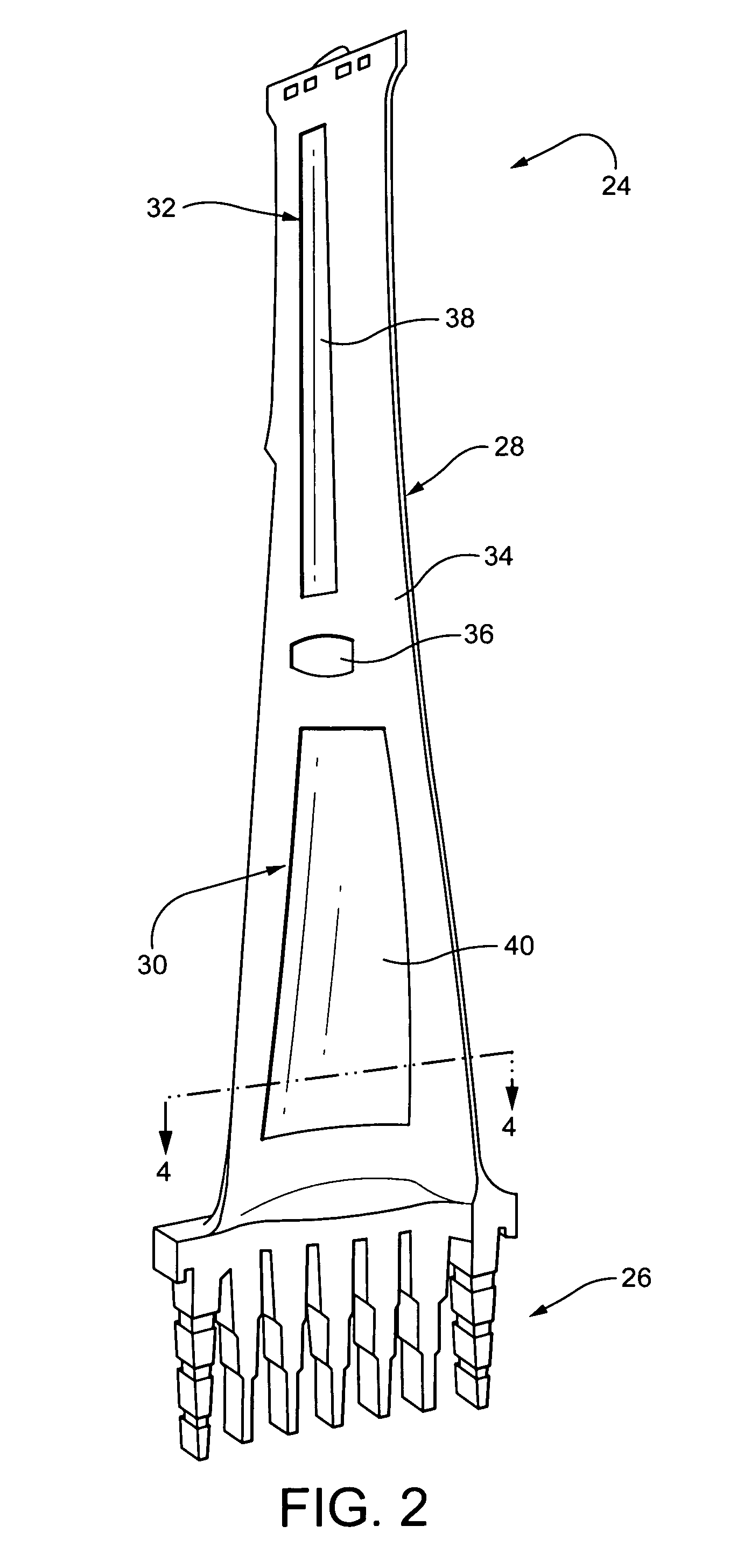
[0017]FIG. 2 schematically shows an example construction of a steam turbine blade 24 in which the invention may be embodied. The steam turbine blade includes a shank portion 26 and an airfoil portion 28. The airfoil portion has an operating temperature range, a design rotational speed, a blade root attached to the shank portion, a blade tip, and a radial axis extending outward toward the blade tip and inward toward the blade root. The shank portion typically includes a dovetail for attachment of the blade to a rotor disc (FIG. 3), and a blade platform for helping to radially contain the steam flow. The ...


PUM

PropertyMeasurementUnit
operating temperatureaaaaaaaaaa
mass densityaaaaaaaaaa
rotational speedaaaaaaaaaa

Abstract

To address certain deficiencies of carbon fiber material as a filler in a hybrid blade, a glass composite layer is provided as a barrier layer between a carbon fiber resin filler and the metallic main body of the blade. The glass composite layer also advantageously provides a gradient in thermal expansion between the carbon fiber composite and the body of the blade (steel) to reduce interfacial residual stress.

Description

BACKGROUND OF THE INVENTION[0001]The present invention relates generally to gas and steam turbines and, more particularly, to a steam turbine blade composed of two or more components made from different materials.[0002]Steam turbine blades operate in an environment where they are subject to high centrifugal loads and vibratory stresses. Vibratory stresses increase when blade natural frequencies become in resonance with running speed or other passing frequencies (upstream bucket or nozzle count, or other major per / rev features). The magnitude of vibratory stresses when a blade vibrates in resonance is proportional to the amount of damping present in the system (damping is comprised of material, aerodynamic and mechanical components, as well as the vibration stimulus level). For continuously coupled blades, the frequency of vibration is a function of the entire system of blades in a row, and not necessarily that of individual blades within the row.[0003]Furthermore, for turbine bucket...

Claims


Application Information

Patent Timeline
Patent Type & Authority Applications(United States)
IPC IPC(8): F01D5/14
CPCF01D5/282F05D2300/603F05D2240/30F01D5/28F01D5/14F01D5/16F01D25/06
Inventor BURDGICK, STEVEN SEBASTIANLIN, WENDY WEN-LINGMAKINDE, ADEGBOYEGALANAUD, CHRISTOPHEBANSAL, AMITABH
Owner GENERAL ELECTRIC CO
Why Eureka
Try Eureka