Sub-lithographic feature patterning using self-aligned self-assembly polymers

a self-assembly polymer and feature patterning technology, applied in the field of semiconductor technology, can solve the problems of large, low device density on the integrated chip, and large order array of repeating structural units formed by self-assembly block copolymers, and achieve the effect of avoiding the use of cmos devices and reducing the number of lithographic tools availabl

Active Publication Date: 2007-12-20
IBM CORP
View PDF4 Cites 133 Cited by
  • Summary
  • Abstract
  • Description
  • Claims
  • Application Information

AI Technical Summary

Problems solved by technology

However, the currently available 0.93 numerical aperture (NA) lithographic tool can only resolve lithographic patterns with contact openings of not less than 100 nm in diameter.
The large contact opening diameter contributes to an undesirable low device density on the integrated chip.
Therefore, the large, ordered array of repeating structural units formed by self-assembling block copolymers could not be used in CMOS devices, because of lack of alignment or registration of the position of individual structure unit.

Method used


Image

  • Sub-lithographic feature patterning using self-aligned self-assembly polymers
  • Sub-lithographic feature patterning using self-aligned self-assembly polymers
  • Sub-lithographic feature patterning using self-aligned self-assembly polymers

Examples


Embodiment Construction

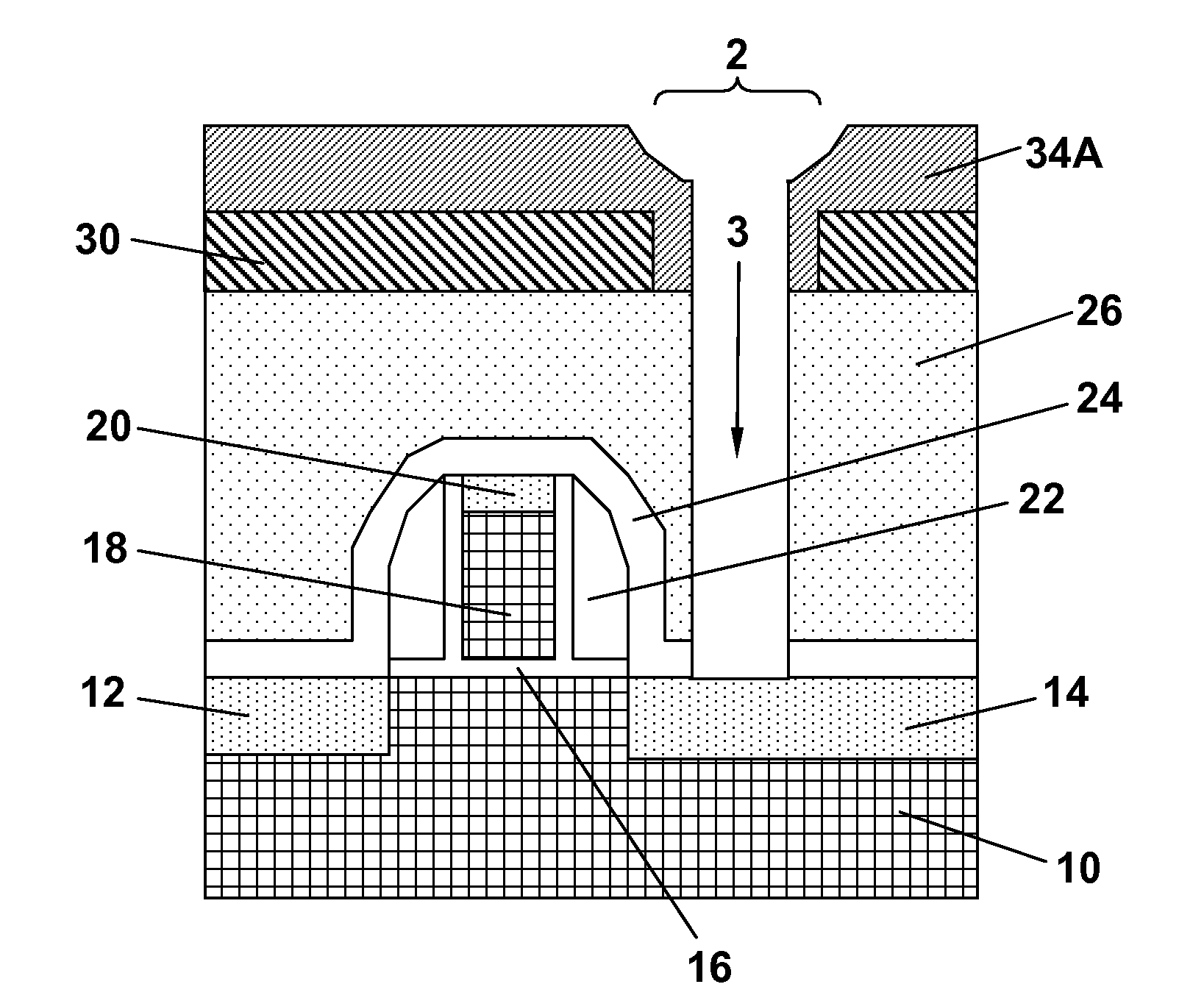
[0033]In the following description, numerous specific details are set forth, such as particular structures, components, materials, dimensions, processing steps and techniques, in order to provide a thorough understanding of the present invention. However, it will be appreciated by one of ordinary skill in the art that the invention may be practiced without these specific details. In other instances, well-known structures or processing steps have not been described in detail in order to avoid obscuring the invention.

[0034]It will be understood that when an element as a layer, region or substrate is referred to as being “on” or “over” another element, it can be directly on the other element or intervening elements may also be present. In contrast, when an element is referred to as being “directly on” or “directly over” another element, there are no intervening elements present. It will also be understood that when an element is referred to as being “connected” or “coupled” to another ...


PUM


Abstract

A method for conducting sub-lithography feature patterning of a device structure is provided. First, a lithographically patterned mask layer that contains one or more mask openings of a diameter d is formed by lithography and etching over an upper surface of the device structure. Next, a layer of a self-assembling block copolymer is applied over the lithographically patterned mask layer and then annealed to form a single unit polymer block of a diameter w inside each of the mask openings, provided that w<d. Each single unit polymer block of the present invention is embedded in a polymeric matrix and can be selectively removed against the polymeric matrix to form a single opening of the diameter w in the polymeric matrix inside each of the mask openings. Sub-lithography feature patterning can then be conducted in the device structure using the single openings of diameter w.

Description

FIELD OF THE INVENTION[0001]The present invention generally relates to sub-lithographic feature patterning for semiconductor technology using self-aligned self-assembly polymers.BACKGROUND OF THE INVENTION[0002]The current state of the art and future CMOS technology requires sub-50 nm metal contacts for connecting the CMOS devices, such as field effect transistors (FETs), to the back-end-of-line (BEOL) wiring. However, the currently available 0.93 numerical aperture (NA) lithographic tool can only resolve lithographic patterns with contact openings of not less than 100 nm in diameter. Future generation of 1.2 NA lithographic tool is expected to print lithographic patterns with contact openings of about 70 nm to 80 nm in diameter. The large contact opening diameter contributes to an undesirable low device density on the integrated chip.[0003]Therefore, there is a need for reducing the CMOS contact opening diameter to even below the resolutions of the lithographic tools, i.e., there i...

Claims


Application Information

Patent Timeline
Patent Type & Authority Applications(United States)
IPC IPC(8): H01L21/4763H01L21/31
CPCH01L21/0332H01L21/0337H01L21/76816H01L21/31144H01L21/0338G03F7/0002H01L23/485
Inventor YANG, HAININGLI, WAI-KIN
Owner IBM CORP
Why Eureka
Try Eureka