Vehicle brake control system and method

a technology of brake control system and vehicle, which is applied in the direction of braking system, pedestrian/occupant safety arrangement, instruments, etc., can solve the problems that the control provided by the vehicle brake control system may not be optimal, and achieve the effect of reducing braking force and improving accuracy

Inactive Publication Date: 2007-12-20
NISSAN MOTOR CO LTD
View PDF4 Cites 33 Cited by
  • Summary
  • Abstract
  • Description
  • Claims
  • Application Information

AI Technical Summary

Benefits of technology

[0007]The present invention was conceived in view of this disadvantage in the above mentioned vehicle brake control system. One object of the present invention is to improve the accuracy with a vehicle brake control system can determine that a detected preceding object can be avoided by steering away from the preceding object with a reduced braking force acting on the vehicle in situations in which it is difficult to avoid the preceding object with a braking force alone.

Problems solved by technology

Since the vehicle brake control system just described does not determine whether or not the vehicle can avoid the preceding object by steering with the braking force of the vehicle being lowered, there are situations in which the reduced braking force control may be executed even though the obstacle cannot be avoided by steering with the reduced braking force control being executed.
Thus, the avoidance control provided by this vehicle brake control system may not be optimal in certain situations.

Method used


Image

  • Vehicle brake control system and method
  • Vehicle brake control system and method
  • Vehicle brake control system and method

Examples


first embodiment

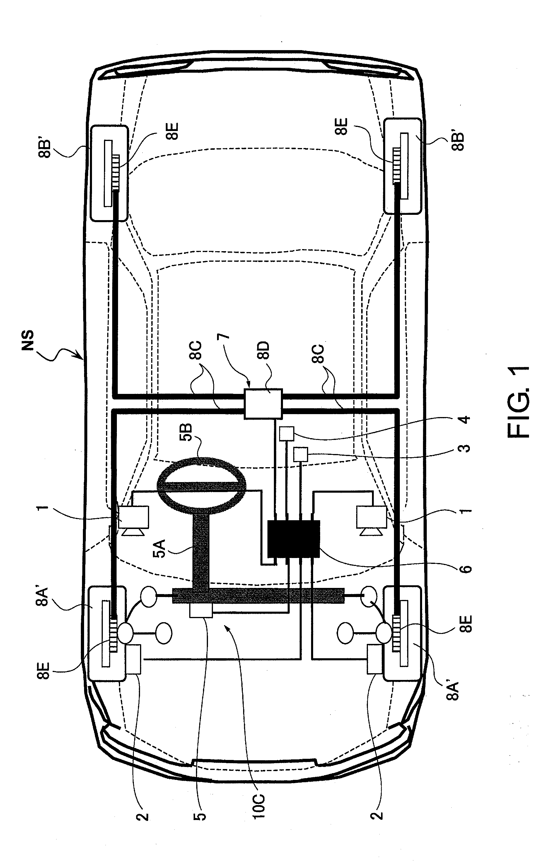
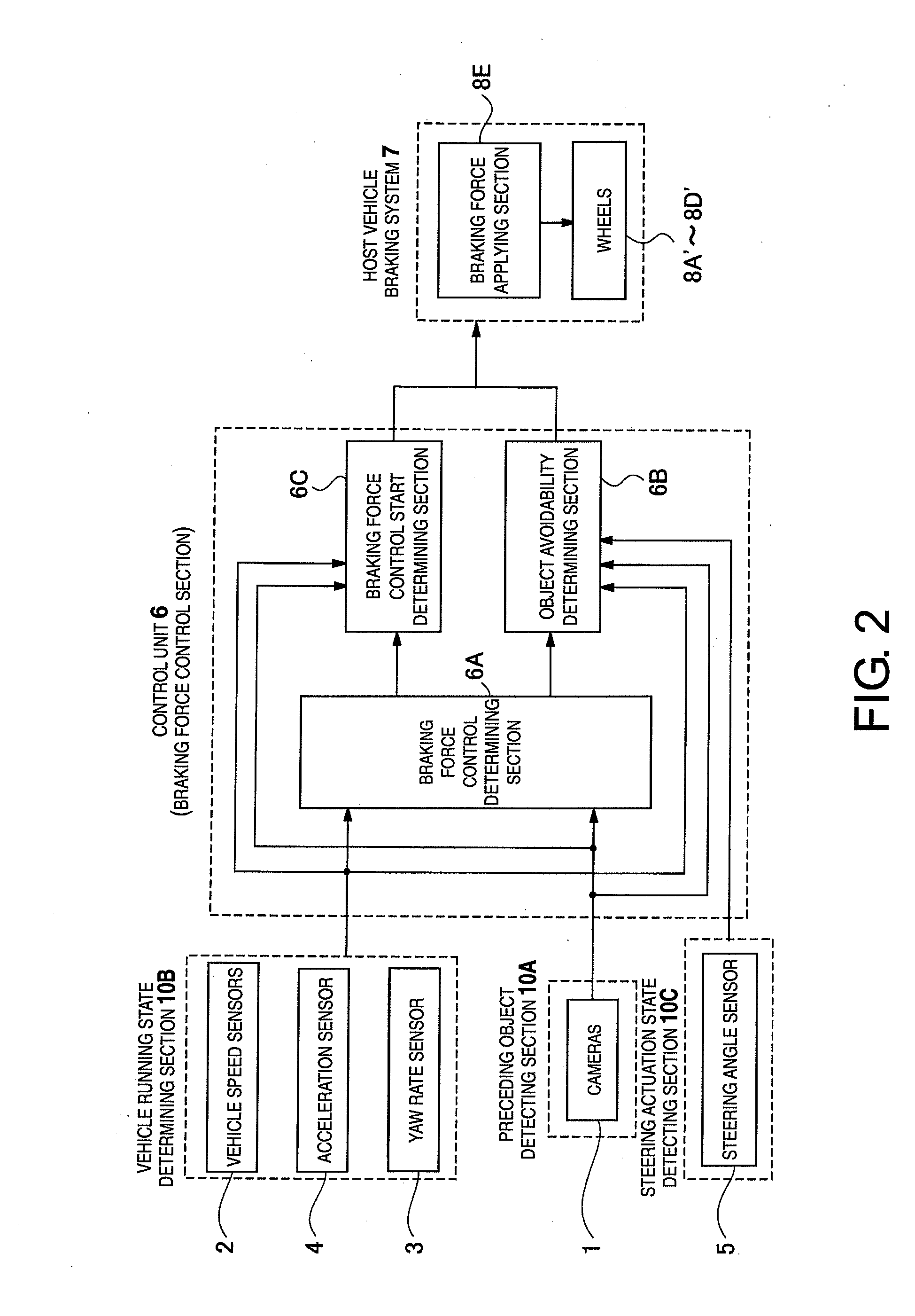
[0025]Referring initially to FIG. 1, a vehicle NS (hereinafter also called “the host vehicle”) is illustrated that is equipped with a vehicle brake control system in accordance with a first embodiment of the present invention. As shown in FIG. 1, the vehicle brake control system basically includes a pair of cameras 1, a pair of vehicle speed sensors 2, a yaw rate sensor 3, an acceleration sensor 4, a steering angle sensor 5, a control unit 6, a host vehicle braking system 7, a pair of front wheels 8A′, and a pair of rear wheels 8B′. The front and rear wheels 8A′ and 8B′ as used herein includes their respective tires. These constituent components are arranged in appropriate locations of the host vehicle NS to carry out the present invention, as will now be explained.

[0026]The cameras 1 are mounted inside a frontward portion of the cabin such that they can photograph the road situation in front of the host vehicle NS. The cameras 1 function as a preceding object detecting section 10A ...

second embodiment

[0094]Referring now to FIG. 8, a vehicle brake control system in accordance with a second embodiment will now be explained. In view of the similarity between the first and second embodiments, the parts of the second embodiment that are identical to the parts of the first embodiment will be given the same reference numerals as the parts of the first embodiment. Moreover, the descriptions of the parts of the second embodiment that are identical to the parts of the first embodiment may be omitted for the sake of brevity.

[0095]In this embodiment, in addition to taking into account operation of the steering wheel, the vehicle brake control system takes into account a brake pedal actuation amount by the driver when determining whether or not to start braking force control. As shown FIG. 8, the vehicle brake control system includes a brake pedal 9 and a master cylinder 10. A pressure sensor 11 for measuring hydraulic pressure is provided in the master cylinder 10 such that operation of the...

third embodiment

[0107]Referring now to FIG. 9, a vehicle brake control system in accordance with a third embodiment will now be explained. In view of the similarity between the prior embodiments and this embodiments, the parts of this embodiment that are identical to the parts of the prior embodiments will be given the same reference numerals as the parts of the prior embodiments. Moreover, the descriptions of the parts of this embodiment that are identical to the parts of the prior embodiments may be omitted for the sake of brevity.

[0108]In particular, the third embodiment is similar to the second embodiment shown in FIG. 8 in that the braking force control is started when all of the condition Equations (1), (2), and (15) are satisfied. However, in the third embodiment, the braking forces generated due to operation of the brake pedal 9 by the driver are not increased when the braking force control start conditions are all satisfied. Furthermore, after the braking force control of the host vehicle ...


PUM


Abstract

A vehicle brake control system is provided with a preceding object detecting section, a running condition detection section, a steering actuation state detecting section, a braking force detecting section, a preceding object avoidability determining section and a braking force control section. The preceding object avoidability determining section determines a possibility of avoiding the preceding object by steering and reducing the current braking force acting on the host vehicle based on the position of the preceding object, the running condition of the host vehicle, the braking force applied to the host vehicle and the steering wheel actuation state that are detected. The braking force control section reduces the current braking force applied by the host vehicle braking system when the preceding object avoidability determining section determines that the preceding object can be avoided by steering and reducing the current braking force acting on the host vehicle.

Description

CROSS-REFERENCE TO RELATED APPLICATIONS[0001]This application claims priority to Japanese Patent Application No. 2006-167397, filed on Jun. 16, 2006. The entire disclosure of Japanese Patent Application No. 2006-167397 is hereby incorporated herein by reference.BACKGROUND OF THE INVENTION[0002]1. Field of the Invention[0003]The present invention generally relates to a vehicle brake control system and method capable of assisting a driver with respect to avoiding an obstacle. More specifically, the present invention relates to a vehicle brake control system and method that aids in determining if a preceding detected obstacle can be avoided by steering way from the preceding object and lowering the braking force acting on the vehicle.[0004]2. Background Information[0005]Vehicle brake control systems have been proposed to determine the possibility of avoiding an obstacle existing in front of a host vehicle in which the system is employed and to control a host vehicle braking system appl...

Claims


Application Information

Patent Timeline
Patent Type & Authority Applications(United States)
IPC IPC(8): G08G1/16B60R21/00B60T7/12
CPCB60T7/22B60T2201/022B60T2201/03B60W10/196G08G1/16B60W30/09B60W2510/20B60W2540/12B60W10/20B60W2540/18G08G1/166
Inventor NISHIRA, HIKARUDEGUCHI, YOSHITAKA
Owner NISSAN MOTOR CO LTD
Why Eureka
Try Eureka