
Method and apparatus for identifying a failure mechanism for a component in a computer system

Active Publication Date: 2007-12-20
ORACLE INT CORP
View PDF9 Cites 73 Cited by
  • Summary
  • Abstract
  • Description
  • Claims
  • Application Information

AI Technical Summary

Benefits of technology

[0014] In a variation on this embodiment, the telemetry signal measured from the component under surveillance can have: (1) low resolution; or (2) low-sampling-rate.

Problems solved by technology

Typically, this is achieved by detecting anomalies in the signals which may potentially lead to system failures.
Unfortunately, a monitoring system that lacks the ability to identify the root cause of a fault cannot provide correct solutions for dealing with the fault.
However, it is not possible to have humans looking at these telemetry signatures on a 24×7 basis.

Method used


Image

  • Method and apparatus for identifying a failure mechanism for a component in a computer system
  • Method and apparatus for identifying a failure mechanism for a component in a computer system
  • Method and apparatus for identifying a failure mechanism for a component in a computer system

Examples


example

[0050]FIG. 5 illustrates an exemplary process for identifying a root cause for a faulty power supply in a server system in accordance with an embodiment of the present invention.

[0051] A known type of degradation in this type of power supplies is characterized by distinctive and reproducible transients in the output voltages which contain a characteristic pattern: a dip followed by a spike. Unfortunately, the time series telemetry signals obtained from these power supplies contain only low-resolution, low-sampling-rate signal values. This low-resolution, low-sampling rate time series contains an incomplete version of the actual failure signature, which is shown in FIG. 5A.

[0052] Note that it is typically difficult to evaluate the characteristics, such as amplitude and duration of the transient behavior based on such noisy and incomplete information.

[0053] However, by using an auto-associative memory, one is able to reconstruct (recall) the complete failure signature of the record...


PUM


Abstract

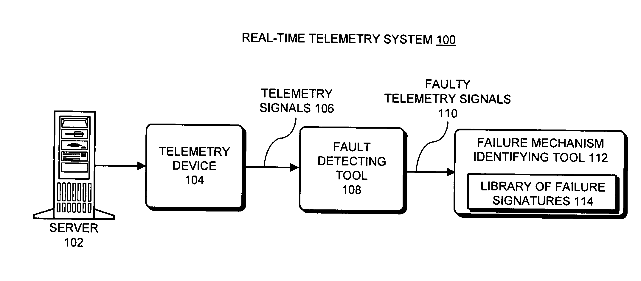
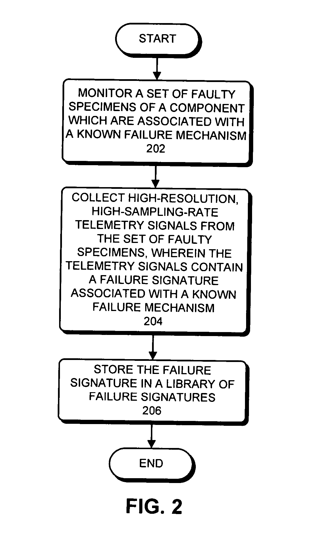
One embodiment of the present invention provides a system that identifies a failure mechanism for a component. The system first constructs a library of failure signatures from a set of components, wherein each failure signature in the library characterizes a known failure mechanism associated with a component in the set of components. Next, the system receives a telemetry signal which is measured from a component under surveillance. The system then determines if there is an anomaly in the telemetry signal. If so, the system performs pattern-matching operations between the telemetry signal and failure signatures in the library. Next, if a match is found, the system identifies the failure mechanism for the component under surveillance based on the matching failure signature.

Description

BACKGROUND [0001] 1. Field of the Invention [0002] The present invention relates to techniques for performing a root-cause analysis on a faulty computer system. More specifically, the present invention relates to a method and an apparatus that automatically identifies a failure mechanism associated with a signal measured from a faulty component in a computer system. [0003] 2. Related Art [0004] Modern server systems are typically equipped with a significant number of sensors which monitor signals during the operation of the server systems. For example, these monitored signals can include temperatures, voltages, currents, and a variety of software performance metrics, including CPU usage, I / O traffic, and memory utilization. Outputs from this monitoring process can be used to generate time series data for these signals which can subsequently be analyzed to determine how well a computer system is operating. [0005] One particularly useful application of this analysis technique is to fa...

Claims


Application Information

Patent Timeline
IPC IPC(8): G06F11/00
CPCG06F1/30G06F11/2252G06F11/0751G06F11/0748
Inventor USYNIN, ALEXANDER V.URMANOV, ALEKSEY M.GROSS, KENNY C.
Owner ORACLE INT CORP
Learn More