Techniques for hardware-assisted multi-threaded processing

a multi-threaded processing and hardware technology, applied in multi-programming arrangements, instruments, computations using denominational number representations, etc., can solve the problems of increasing the number of processors needed to support line rate processing, multi-threaded processors available commercially, and thread switching involves many clock cycles

Active Publication Date: 2007-12-20
CISCO TECH INC
View PDF36 Cites 65 Cited by
  • Summary
  • Abstract
  • Description
  • Claims
  • Application Information

AI Technical Summary

Problems solved by technology

The idle time introduced by the frequent long-latency memory accesses increases the number of processors needed to support line rate processing.
While suitable for many purposes, the commercially available multi-threaded processors suffer some disadvantages.
One disadvantage is that thread switching involves many clock cycles as all the contents of multiple registers used by the processor as operands and results of instructions are swapped, i.e., moved off the processor to a more spacious memory (that is often off the chip and requires use of a shared bus) and replaced by contents of registers for a different thread in another portion of that memory.
These multi-threaded processors also consume clock cycles to swap instructions and data in local caches to other more spacious memory, such as off-chip memory.
These extra cycles reduce the effectiveness of each multi-threaded processor and requires the deployment of more such processors to achieve line rate processing in a router
Another disadvantage is that some multi-threaded processors use a thread scheduler process that forces a thread switch at arbitrary times, such as after a certain number of clock cycles unrelated to when the thread issues a long-latency memory operation.
Such processors incur the cost of thread switching without the benefit of reduced idle time on the processor.
However, the design and development of a new processor is an extremely costly effort that takes many years.

Method used


Image

  • Techniques for hardware-assisted multi-threaded processing
  • Techniques for hardware-assisted multi-threaded processing
  • Techniques for hardware-assisted multi-threaded processing

Examples


Embodiment Construction

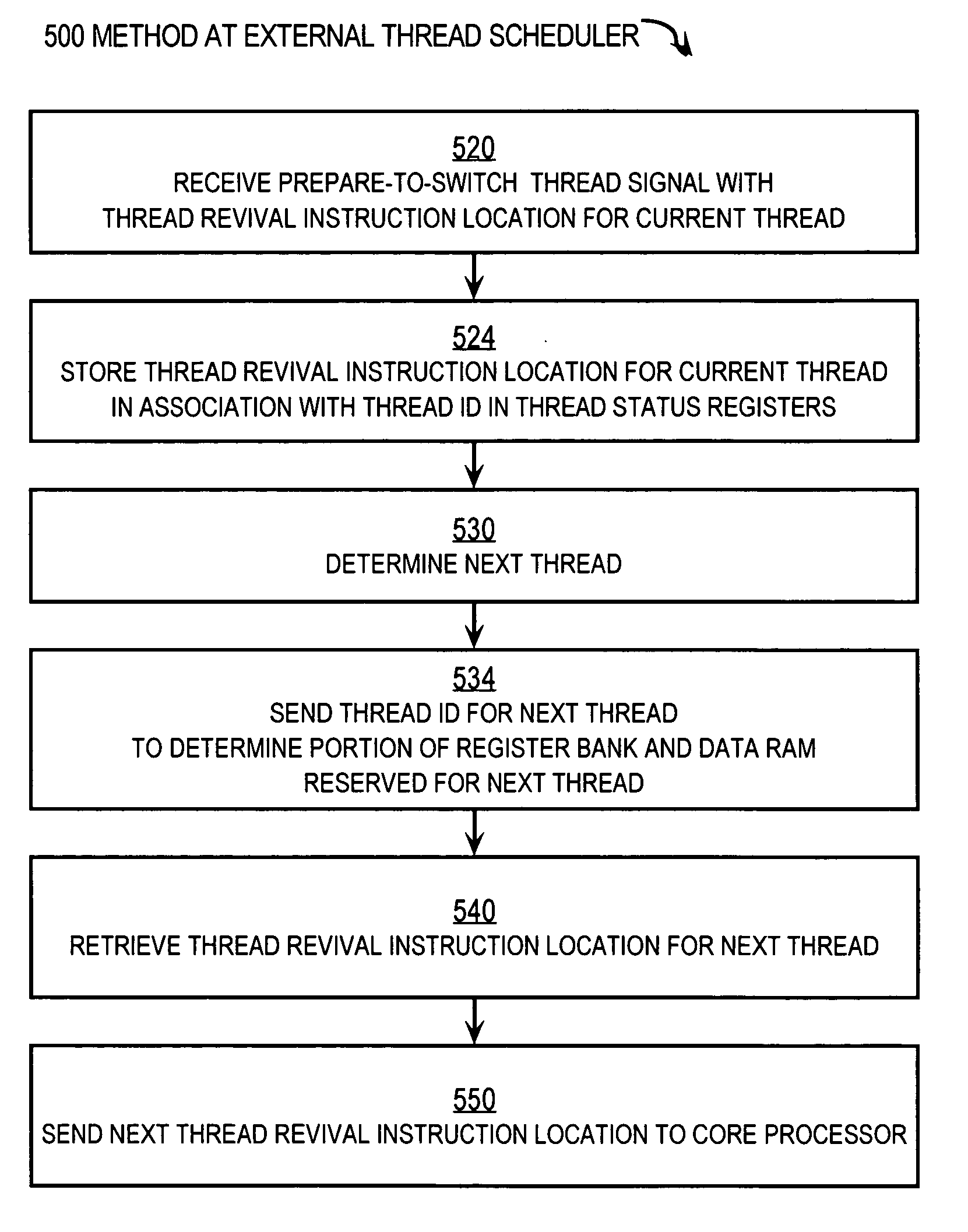
[0021]Techniques are described for switching among processing threads using a hardware assist. In the following description, for the purposes of explanation, numerous specific details are set forth in order to provide a thorough understanding of the present invention. It will be apparent, however, to one skilled in the art that the present invention may be practiced without these specific details. In other instances, well-known structures and devices are shown in block diagram form in order to avoid unnecessarily obscuring the present invention.

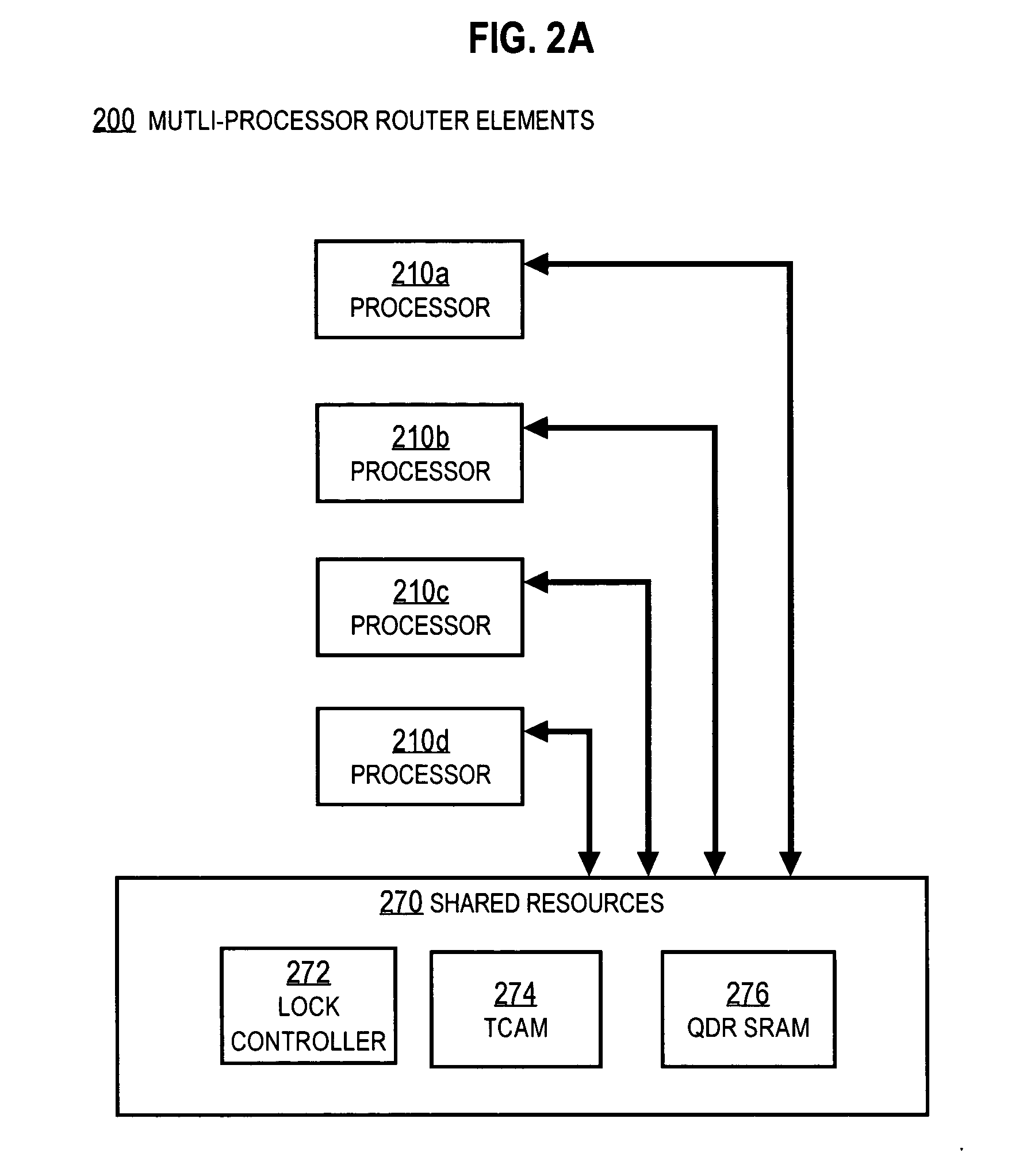
[0022]Embodiments of the invention are described in detail below in the context of a data packet switching system on a router that has four processors, each allowing up to four threads that share use of a TCAM and QDR for updating routing tables while forwarding data packets at a high speed line rate. However, the invention is not limited to this context. In various other embodiments, more or fewer processors allowing more or fewer threads sh...


PUM


Abstract

Techniques for processing each of multiple threads that share a core processor include receiving an intra-thread register address from the core processor. This address contains C bits for accessing each of 2c registers for each thread. A thread ID is received from a thread scheduler external to the core processor. The Thread ID contains T bits for indicating a particular thread for up to 2T threads. A particular register is accessed in a register bank that has 2(C+T) registers using an inter-thread address that includes both the intra-thread register address and the thread ID. The particular register holds contents for the intra-thread register address for a thread having the thread ID. Consequently, register contents of all registers of all threads reside in the register bank. Thread switching is accomplished rapidly by simply accessing different slices in the register bank, without swapping contents between a set of registers and memory.

Description

BACKGROUND OF THE INVENTION[0001]1. Field of the Invention[0002]The present invention relates to using hardware to assist in multi-threaded processing and, in particular, to using hardware to select a sliding window in a register bank and data random access memory (RAM) when switching between threads in fewer clock cycles than in conventional thread switching mechanisms.[0003]2. Description of the Related Art[0004]Many processors are designed to reduce idle time by swapping multiple processing threads. A thread is a set of data contents for processor registers and memory and a sequence of instructions to operate on those contents that can be executed independently of other threads. Some instructions involve sending a request or command to another component of the device or system, such as input / output devices or one or more high valued, high-latency components that take many processor clock cycles to respond. Rather than waiting idly for the other component to respond, the processor...

Claims


Application Information

Patent Timeline
Patent Type & Authority Applications(United States)
IPC IPC(8): G06F9/46
CPCG06F9/30123G06F9/462G06F9/3851
Inventor JETER, ROBERTGAMER, TREVORLEE, WILLIAMSMITH, SCOTTGOSS, GEGORY
Owner CISCO TECH INC
Why Eureka
Try Eureka