
Fluid sensor with mechanical positional feedback

a positional feedback and sensor technology, applied in the direction of liquid/fluent solid measurement, instrumentation, volume/mass flow by differential pressure, etc., can solve the problems of negatively affecting fluid flow, invasive and/or expensive, easy to plug orifices,

Inactive Publication Date: 2007-12-27
PRECISION PUMPING SYST
View PDF14 Cites 29 Cited by
  • Summary
  • Abstract
  • Description
  • Claims
  • Application Information

AI Technical Summary

Benefits of technology

[0009]A fluid sensing system is herein disclosed as including a sensor port and a sensor having a first end mounted to the sensor port and a second end configured to deflect in a predetermined arc when exposed to a fluid force. An electric signal is propagated through the sensor during operation of the fluid sensing system. T

Problems solved by technology

Current sensor devices and technology depends on many different methods of acquiring fluid property measurements from various apparatuses that are either problematically invasive and / or expensive.
Devices that rely on an invasive approach create a large differential pressure within the fluid stream that negatively impedes fluid flow.
Other devices rely on very small, easily plugged orifices or contain multiple parts that rotate or move with respect to each other, such as bearings, that are susceptible to failure due to material on material contact.
Such devices are expensive to manufacture, assemble and repair.
Friction forces acting on the device parts results in the worn away material being carried downstream, potentially causing extensive damage to other components, systems or machines.
Conventional sensor devices are only able to measure a fluid flow in a single direction, or require at least two sensors to measure opposite fluid flow.

Method used


Image

  • Fluid sensor with mechanical positional feedback
  • Fluid sensor with mechanical positional feedback
  • Fluid sensor with mechanical positional feedback

Examples


Embodiment Construction

[0025]The measurement of fluid properties such as fluid flow rate, fluid pressures and fluid levels, has a wide range of uses and application in industry. For example, a municipal water works may want to monitor how much water is being consumed by its customers. A sewage treatment plant may want to monitor how much waster water is being transferred to a holding tank. Some uses include determining a fluid flow or pressure in an oil or natural gas line. Other applications include measuring a fluid level in a pipe, tank, river or even a lake. Measuring fluid properties therefore has the potential to provide many commercial benefits. The following embodiments provide examples of measurement devices and methods of measuring fluid properties for any number of different types of fluids, including liquids and gases.

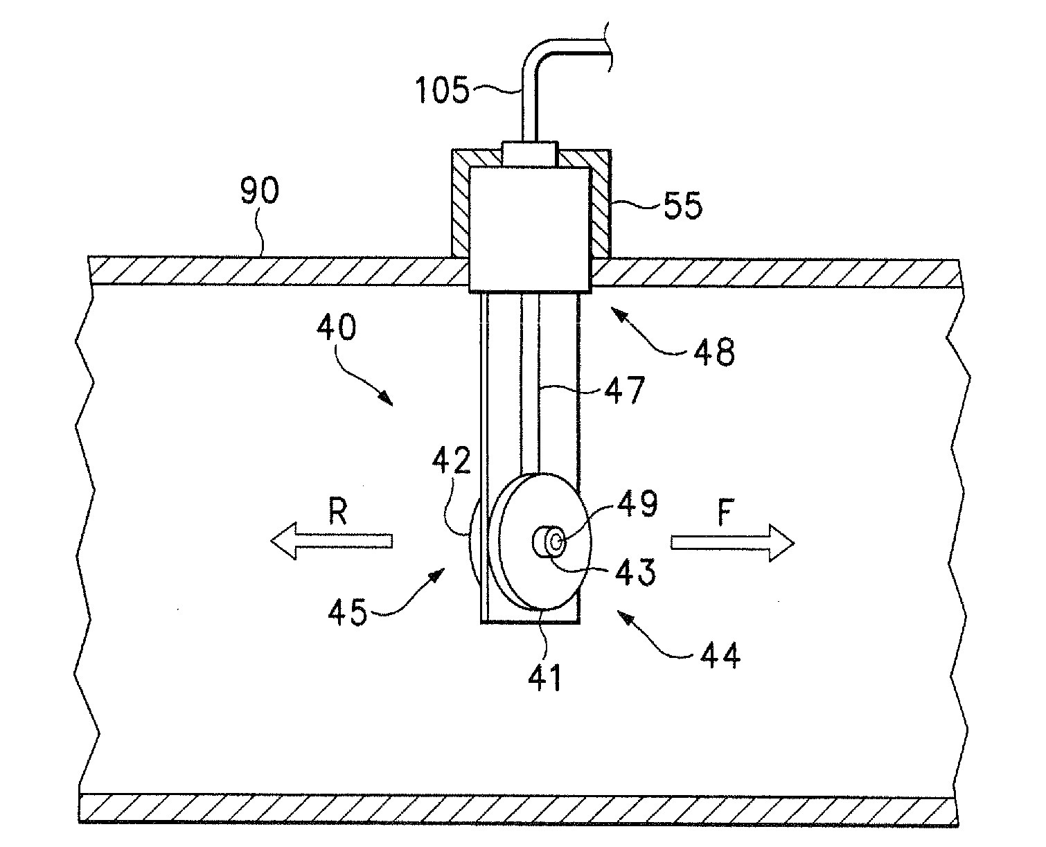
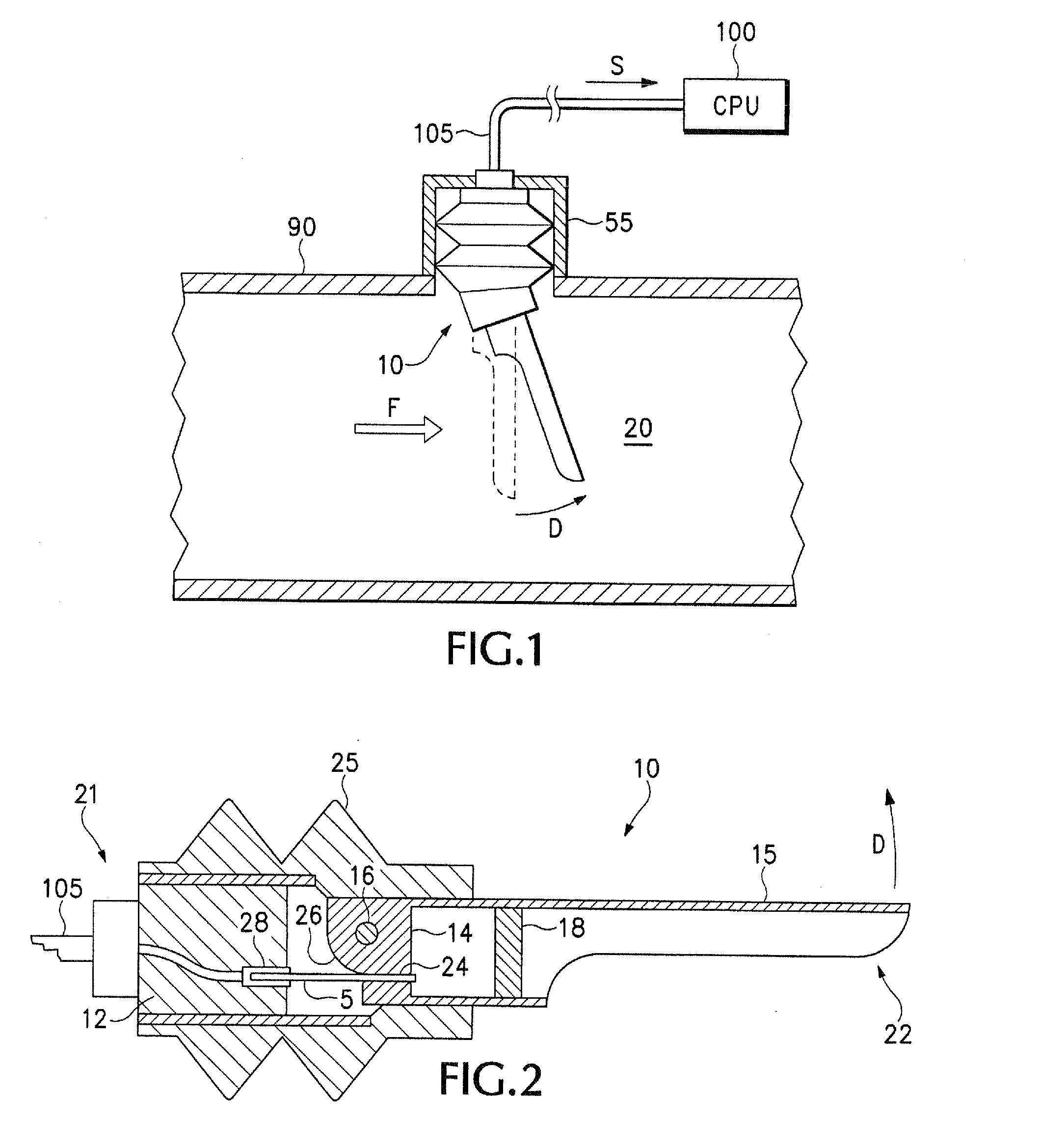
[0026]FIG. 1 is a diagram illustrating an example fluid sensing system 10 mounted in a fluid carrier 90. The fluid carrier 90 may be a pipe, line, conduit, ditch, canal, or river...


PUM


Abstract

A fluid detection device is herein disclosed as including a sensor mount, a flexible deflection sensor rigidly connected to the sensor mount and a stiffener. The stiffener is arranged together with the flexible deflection sensor such that the flexible deflection sensor is preconfigured to deform in a predetermined manner when the fluid detection device is exposed to a fluid. An amount of the deformation of the flexible deflection sensor determines a property of the fluid.A pressure sensing apparatus is herein disclosed as including a rigid perimeter, a flexible membrane forming a surface area bounded by the perimeter, and a sensing means in communication with the flexible membrane. The flexible membrane is configured to elastically deform when a pressure force is exerted on the surface area, and the sensing means is configured to measure an amount of deformation of the flexible membrane.

Description

CROSS REFERENCE TO RELATED APPLICATION[0001]This application claims priority from U.S. Provisional patent application Ser. No. 60 / 804,548 filed Jun. 12, 2007, titled Flow Sensor With Mechanical Positional Feedback Device and Method of Sensing Flow Rate Using Same, the disclosure of which is herein incorporated by reference in its entirety.BACKGROUND[0002]1. Technical Field[0003]This disclosure relates generally to fluid measurement and detection devices, including methods of sensing fluid flow, fluid levels and pressure.[0004]2. Description of the Related Art[0005]Current sensor devices and technology depends on many different methods of acquiring fluid property measurements from various apparatuses that are either problematically invasive and / or expensive. Devices that rely on an invasive approach create a large differential pressure within the fluid stream that negatively impedes fluid flow. Other devices rely on very small, easily plugged orifices or contain multiple parts that r...

Claims


Application Information

Patent Timeline
IPC IPC(8): G01F1/05
CPCG01F1/28G01F1/38G01P5/04G01F23/68G01F1/383
Inventor ELLEGOOD, PAUL L.
Owner PRECISION PUMPING SYST
Features
  • Generate Ideas
  • Intellectual Property
  • Life Sciences
  • Materials
  • Tech Scout
  • Unparalleled Data Quality
  • Higher Quality Content
  • 60% Fewer Hallucinations
Learn More