
Method for Melting Magnesium and Melting Apparatus

a technology of magnesium melt and melting apparatus, which is applied in the direction of heat treatment apparatus, furnaces, manufacturing tools, etc., can solve the problems of economic damage, reduced magnesium melt amount, and damage to the furnace, so as to increase the flow rate of the cover gas, reduce the cost, and increase the cost

Inactive Publication Date: 2007-12-27
NIPPON SANSO CORP +1
View PDF2 Cites 6 Cited by
  • Summary
  • Abstract
  • Description
  • Claims
  • Application Information

AI Technical Summary

Benefits of technology

The present invention provides a method and apparatus for melting magnesium while detecting and extinguishing magnesium combustion. This is achieved by measuring the concentration of carbon monoxide in the furnace or gas discharged from the furnace and controlling the supply rate of a cover gas containing carbon dioxide and a fireproof agent based on the concentration of carbon monoxide. The technical effects include preventing magnesium combustion by increasing the flow rate of the cover gas or concentration of the fireproof agent, and detecting and extinguishing magnesium combustion quickly to prevent accidents and improve safety during magnesium melting.

Problems solved by technology

If the magnesium melt bums by any chance, not only the furnace is damaged, an amount of the magnesium melt itself decreases and economical damage is caused, but also safety problem due to a fire hazard is caused.
However, it is difficult to detect combustion of magnesium within a short time from combustion starts by detecting white smoke, temperature increase of the melt, or temperature increase in a furnace, and this has poor reliability.

Method used


Image

  • Method for Melting Magnesium and Melting Apparatus
  • Method for Melting Magnesium and Melting Apparatus
  • Method for Melting Magnesium and Melting Apparatus

Examples


experimental example

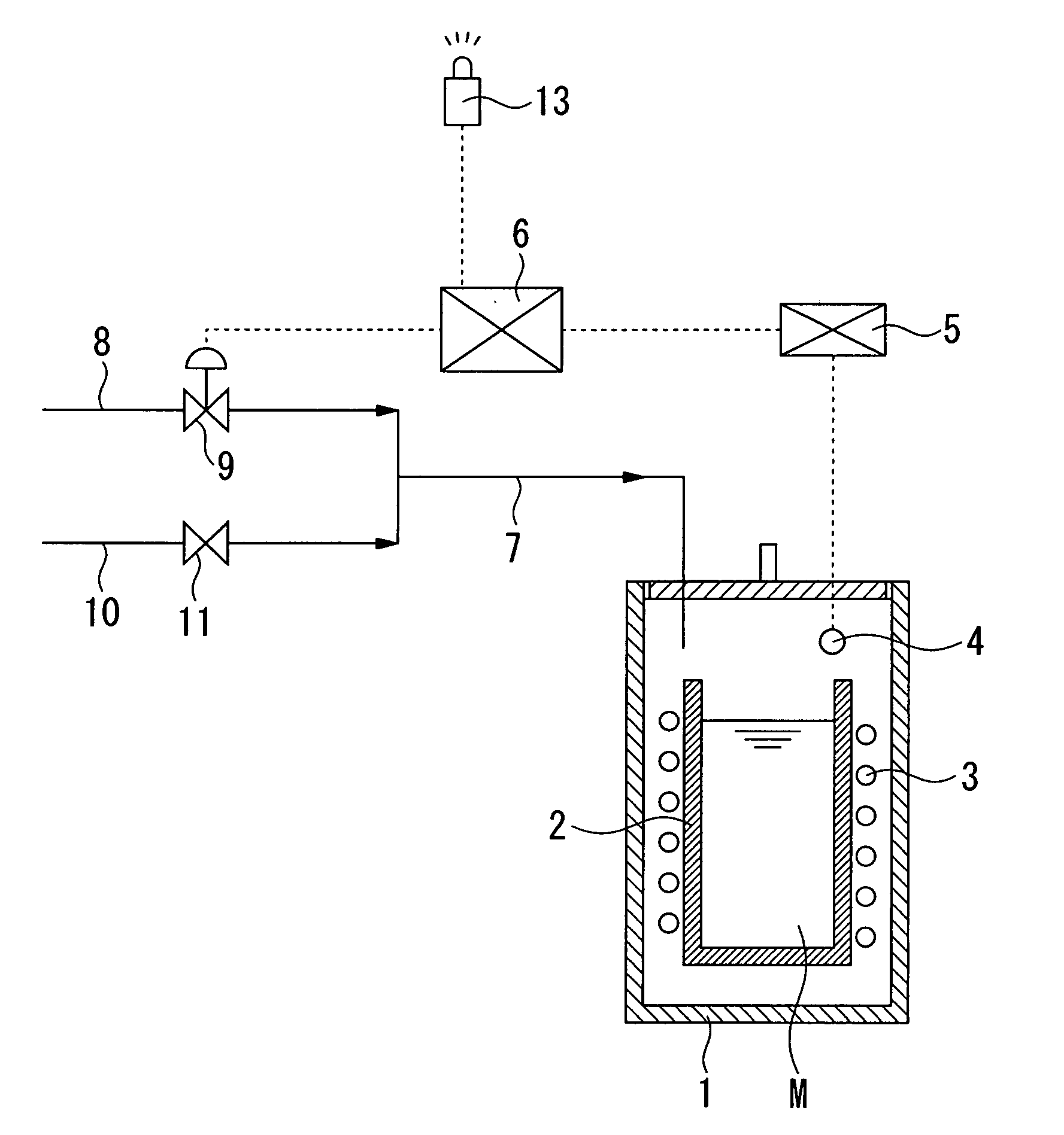
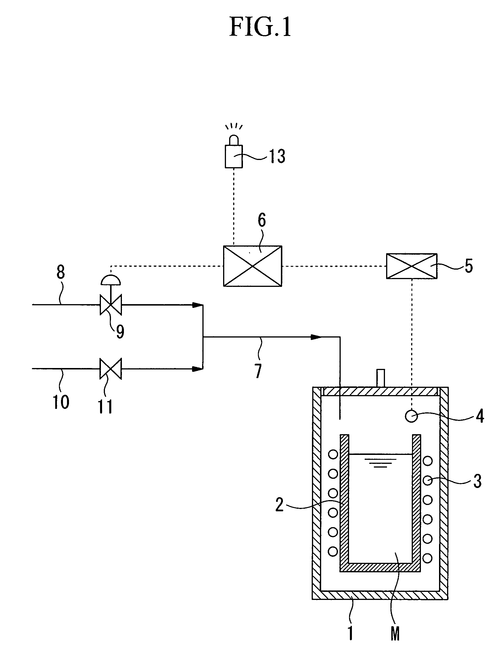
[0056] In this Example, the melting apparatus shown in FIG. 1 was used. The inner diameter of the furnace 1 was 300 mm, and the height was 670 mm. The inside of the furnace 1 could be watched through the heat-resistant glass in the furnace cover.

[0057] The crucible 2 having an inner diameter of 200 mm and a height of 300 mm was positioned in the furnace 1. A magnesium melt, which was obtained by melting 4.7 kg of magnesium alloy (AD91D), was put in the crucible 2. The temperature of the magnesium melt was maintained at 680° C.

[0058] A diluted gas, which was obtained by diluting 1,1,1,2,2,4,4,5,5,5,-nonafluoro-4-(trifluoromethyl)-3-pentanone which is a fireproof agent with carbon dioxide such that the concentration be 200 ppm, was used as a cover gas. The cover gas was supplied to the furnace 1 from the pipe 7 at a rate of 7.5 litter / min. The concentration of carbon monoxide in the furnace 1 was measured by the sensor 4 and the carbon monoxide concentration meter 5.

[0059] The vari...


PUM

PropertyMeasurementUnit
diameteraaaaaaaaaa
diameteraaaaaaaaaa
heightaaaaaaaaaa

Abstract

An object of the present invention is to provide a melting method for magnesium or a magnesium alloy which detects certainly and immediately combustion of a magnesium melt and emits alarm immediately based on the detection results, and extinguishes immediately the magnesium combustion, in order to achieve the object, the present invention provide a method for melting magnesium while supplying a cover gas containing carbon dioxide and a fireproof agent in a furnace for melting magnesium and obtaining a magnesium melt to cover the surface of the magnesium melt, wherein concentration of carbon monoxide in the furnace or gas discharged from the furnace is measured and magnesium combustion in the furnace is detected based on the concentration of carbon monoxide.

Description

TECHNICAL FIELD [0001] The present invention relates to a method and a melting apparatus for melting magnesium or a magnesium alloy and obtaining a magnesium melt or a magnesium alloy melt, in which combustion at the surface of the magnesium melt or the magnesium alloy melt is detected and rapidly extinguished. [0002] Priority is claimed on Japanese Patent Application No. 2005-012580 filed on Jan. 20, 2005, the contents of which are incorporated herein by reference. BACKGROUND ART [0003] When magnesium or a magnesium alloy (hereinafter “magnesium” means both magnesium and a magnesium alloy in the present invention) is melted in a furnace to obtain a magnesium melt, the vicinity of the surface of the melt has been covered with a cover gas in order to prevent combustion of magnesium at the melt surface. [0004] Examples of the cover gas include a gas in which a fireproof agent such as sulfur hexafluoride, and sulfur dioxide is diluted with an inactive gas such as nitrogen. [0005] A rea...

Claims


Application Information

Patent Timeline
Patent Type & Authority Applications(United States)
IPC IPC(8): C22B9/00C22B26/22
CPCB22D21/007C22B26/22C22B9/006C22B9/003Y02P10/25B22D21/04C22B9/16
Inventor SANUI, HIROSHINOMURA, YUJIKATO, TORUNAKAMURA, TORU
Owner NIPPON SANSO CORP
Learn More