Substrate processing method and substrate processing apparatus

a substrate processing and substrate technology, applied in the direction of cleaning processes and apparatus, chemistry apparatus and processes, cleaning using liquids, etc., can solve the problems of micro patterns pulling each other, collapse, and not being able to dissolve ipa in deionized water sufficiently, so as to prevent the destruction of the patterns and facilitate the drying of the surface

Inactive Publication Date: 2007-12-27
DAINIPPON SCREEN MTG CO LTD
View PDF10 Cites 55 Cited by
  • Summary
  • Abstract
  • Description
  • Claims
  • Application Information

AI Technical Summary

Benefits of technology

[0015]In addition, the cleaning apparatuses described in JP-A-9-38595 and JP-A-3-209715, at the time of supplying IPA or the IPA solution to the substrate surface after rinsing processing, a relatively great amount of deionized water adheres to the substrate surface. Hence, if IPA or the IPA solution is supplied to the substrate surface in such a condition, IPA gets discharged from the substrate to outside before IPA gets dissolved sufficiently in deionized water which adheres to the inside of the gaps between the patterns which are formed on the substrate surface. This makes it impossible to sufficiently prevent destruction of the patterns and generation of watermarks during drying of the substrate.
[0016]The invention has been made in light of the problems addressed above, and accordingly aims at realization of favorable drying of a surface of a substrate while suppressing the consumption amount of an organic solvent component in a substrate processing method and a substrate processing apparatus which dry, using the organic solvent component such as IPA, the substrate surface which is wet with a liquid.

Problems solved by technology

By the way, while patterns formed on a surface of a substrate have become increasingly finer at a rapid pace over the recent years, this pattern miniaturization has led to a new problem during substrate processing.
Namely, the problem that micro patterns pull each other and collapse during execution of drying processing.
However, Rotagoni drying gives rise to the following problem since a substrate is dried while rotating the substrate.
In short, even though IPA vapor is supplied to a surface of the substrate, IPA vapor is discharged immediately from the substrate due to the influence of an air flow which develops as the substrate rotates, and it is not therefore possible to sufficiently dissolve IPA in deionized water which adheres to the substrate surface.
As a result, the substrate surface is dried before IPA is dissolved sufficiently in deionized water which adheres to the inside of the gaps between patterns which are formed on the substrate surface, and hence, pattern destruction could not be prevented satisfactorily.
This leaves a problem that for removal of a processing liquid (e.g., a chemical solution, a liquid developer, etc.) and unwanted substances adhering to the substrate surface, a comparable rinsing time is required and the consumption amount of IPA accordingly increases.
Further, while IPA contains particles to a certain extent, if the amount of supplied IPA to a substrate becomes large, the particles contained in IPA could build up on a substrate and contaminate the substrate, which is a problem.

Method used


Image

  • Substrate processing method and substrate processing apparatus
  • Substrate processing method and substrate processing apparatus
  • Substrate processing method and substrate processing apparatus

Examples


first embodiment

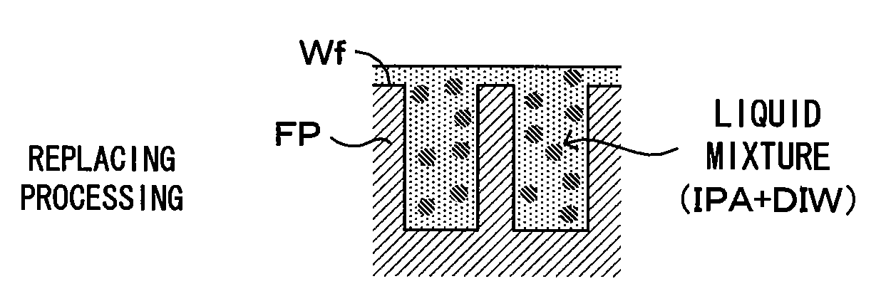
[0049]FIG. 4 is a diagram showing a first embodiment of a substrate processing apparatus according to the invention. FIG. 5 is a block diagram which shows a control configuration of the substrate processing apparatus which is shown in FIG. 4. This substrate processing apparatus is a substrate processing apparatus of the single wafer type which is used in cleaning processing which is for removing contaminants adhering to a surface Wf of a substrate W such as a semiconductor wafer. To be more exact, this is an apparatus in which after chemical processing with a chemical solution of a hydrofluoric acid or the like and rinsing processing with a rinsing liquid such as DIW of the surface Wf of the substrate W of which micro patterns of poly-Si are formed on the surface Wf, the substrate W wet with the rinsing liquid is subjected to replacing processing which will be described later, and the substrate W is dried.

[0050]This substrate processing apparatus comprises a spin chuck 1 which holds...

second embodiment

[0087]FIG. 10 is a diagram showing a second embodiment of a substrate processing apparatus according to the invention.

[0088]FIG. 11 is a block diagram which shows a control configuration of the substrate processing apparatus which is shown in FIG. 10. A major difference of the substrate processing apparatus according to the second embodiment from that according to the first embodiment is that a blocking member 9 functioning as the “atmosphere blocker” of the invention is disposed at a position above the spin chuck 1. The other structures and operations are similar to those according to the first embodiment, and therefore, will merely be denoted at the same reference symbols but will not be described.

[0089]The blocking member 9 is a disk-shaped member which has an opening in its central section and disposed at a position above the spin chuck 1. A lower surface (bottom surface) of the blocking member 9 is an opposed surface which is opposed and approximately parallel to the substrate ...

third embodiment

[0097]FIGS. 12A, 12B, and 12C are diagrams showing a third embodiment of a substrate processing apparatus according to the invention. A major difference of the substrate processing apparatus according to the third embodiment from that according to the first and second embodiments is that a pre-drying step is executed after the replacing step but before the drying step. The other structures and operations are similar to those according to the second embodiment, and therefore, will merely be denoted at the same reference symbols but will not be described.

[0098]In this embodiment, the following pre-drying step is executed after replacement with the liquid mixture (replacing step) but before drying of the substrate W (drying step). First, the liquid mixture is supplied to the substrate surface Wf, and a puddle-like liquid mixture layer 21 is formed all over the substrate surface (FIG. 12A). Following this, a gas discharge nozzle 8 blows a nitrogen gas toward a central section of the sur...


PUM


Abstract

After rinsing, while rotating a substrate, a front layer part of a rinsing liquid (DIW) adhering to a substrate surface is drained and removed from the substrate surface. This is followed by supply to the substrate surface of a liquid mixture which is obtained by mixing IPA and DIW together. Since a majority of the rinsing liquid on the substrate surface is removed off from the substrate surface, even when micro patterns are formed on the substrate surface, the liquid mixture replaces the liquid component adhering to the gaps between the patterns. Further, the IPA concentration in the liquid mixture supplied to the substrate surface is set to 50% or below. Hence, it is possible to effectively prevent destruction of the patterns while suppressing the consumption amount of

Description

CROSS REFERENCE TO RELATED APPLICATION[0001]The disclosure of Japanese Patent Applications No. 2006-176472 filed Jun. 27, 2006 and No. 2006-247923 filed Sep. 13, 2006 including specification, drawings and claims is incorporated herein by reference in its entirety.BACKGROUND OF THE INVENTION[0002]1. Field of the Invention[0003]The present invention relates to a substrate processing method of and a substrate processing apparatus for drying a surface of a substrate which is wet with a liquid. Substrates to be dried include semiconductor wafers, glass substrates for photomask, glass substrates for liquid crystal display, glass substrates for plasma display, substrates for optical disks, etc.[0004]2. Description of the Related Art[0005]Numerous drying methods have already been proposed which aim at removal of a rinsing liquid adhering to a surface of a substrate after chemical processing using a chemical solution and rinsing processing using a rinsing liquid which may be deionized water ...

Claims


Application Information

Patent Timeline
Patent Type & Authority Applications(United States)
IPC IPC(8): B08B3/00B08B7/00
CPCH01L21/67051H01L21/02057H01L21/304
Inventor MIYA, KATSUHIKOIZUMI, AKIRA
Owner DAINIPPON SCREEN MTG CO LTD
Why Eureka
Try Eureka