Ceramic heating elements

a ceramic and resistive technology, applied in the field of ceramic resistive heating elements, can solve the problems of many conventional igniters, which do not consistently meet such requirements, and current ceramic igniters also have suffered electrical failure during use, so as to achieve the effect of increasing the operating li

Inactive Publication Date: 2007-12-27
COORSTEK INC
View PDF10 Cites 17 Cited by
  • Summary
  • Abstract
  • Description
  • Claims
  • Application Information

AI Technical Summary

Benefits of technology

[0009] We now provide ceramic heating elements that include new configurations of regions of differing resistivity. Preferred heating elements of the invention are capable of increased operating lifetimes and robustness. Heating elements of the invention are useful for a variety of applications, including as ignition elements for dry and wet fuels.

Problems solved by technology

Many conventional igniters, however, do not consistently meet such requirements.
For instance, current ceramic igniters also have suffered from electrical failure during use.

Method used


Image

  • Ceramic heating elements
  • Ceramic heating elements
  • Ceramic heating elements

Examples


example 1

Heating Element Fabrication

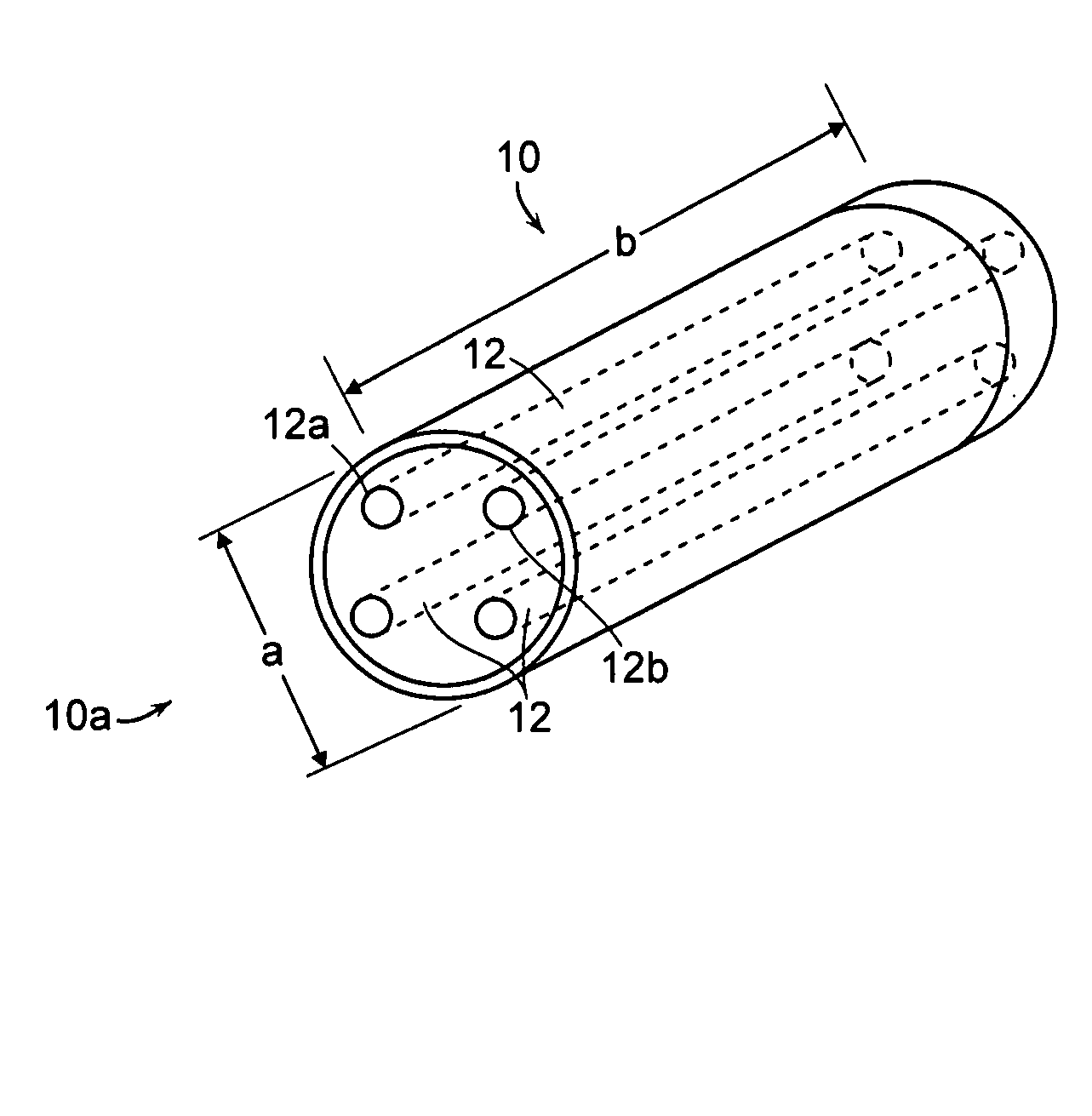
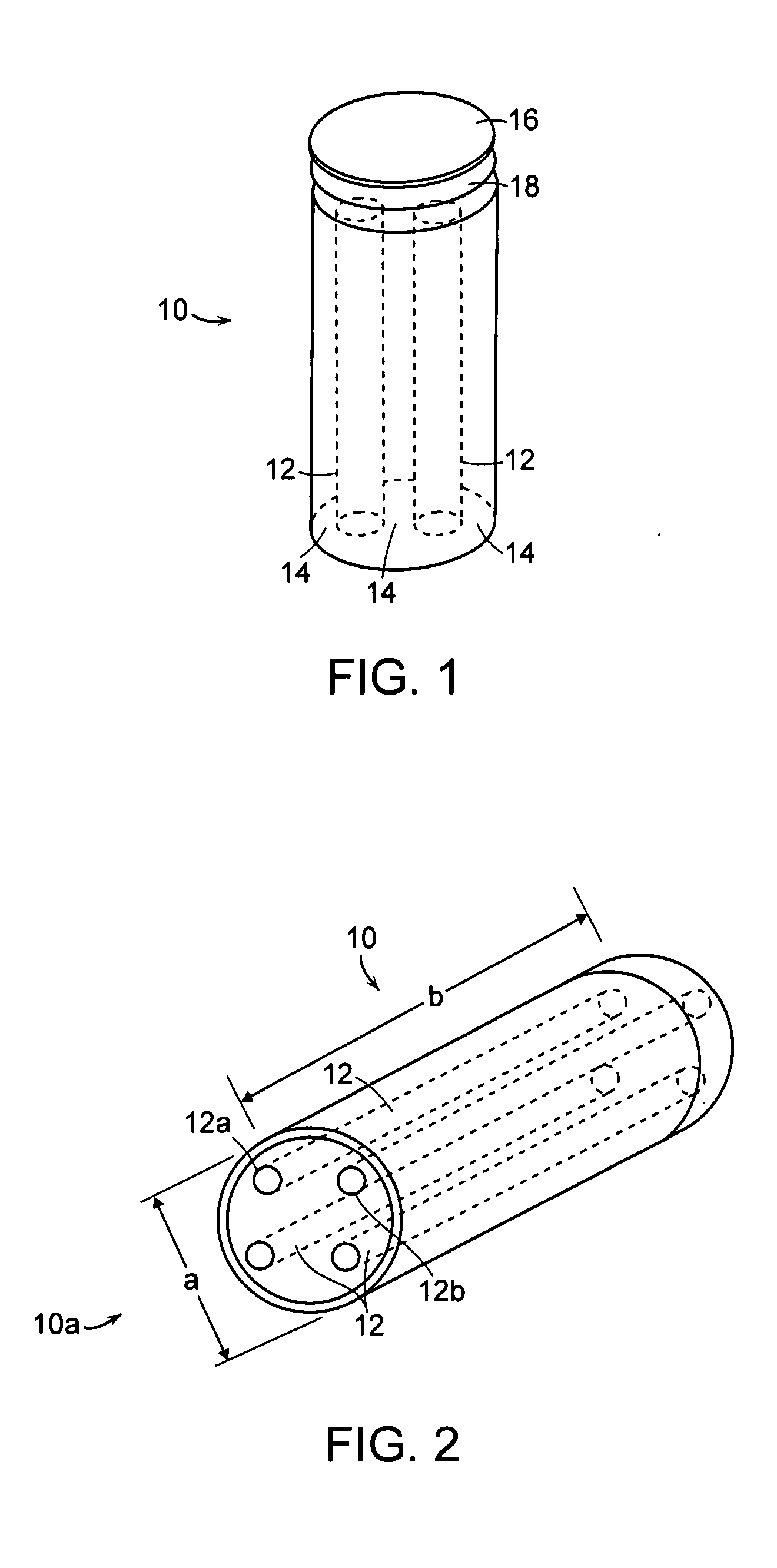
[0092] A heating element of the invention of the general configuration shown in FIG. 2 of the drawings may be prepared as follows.

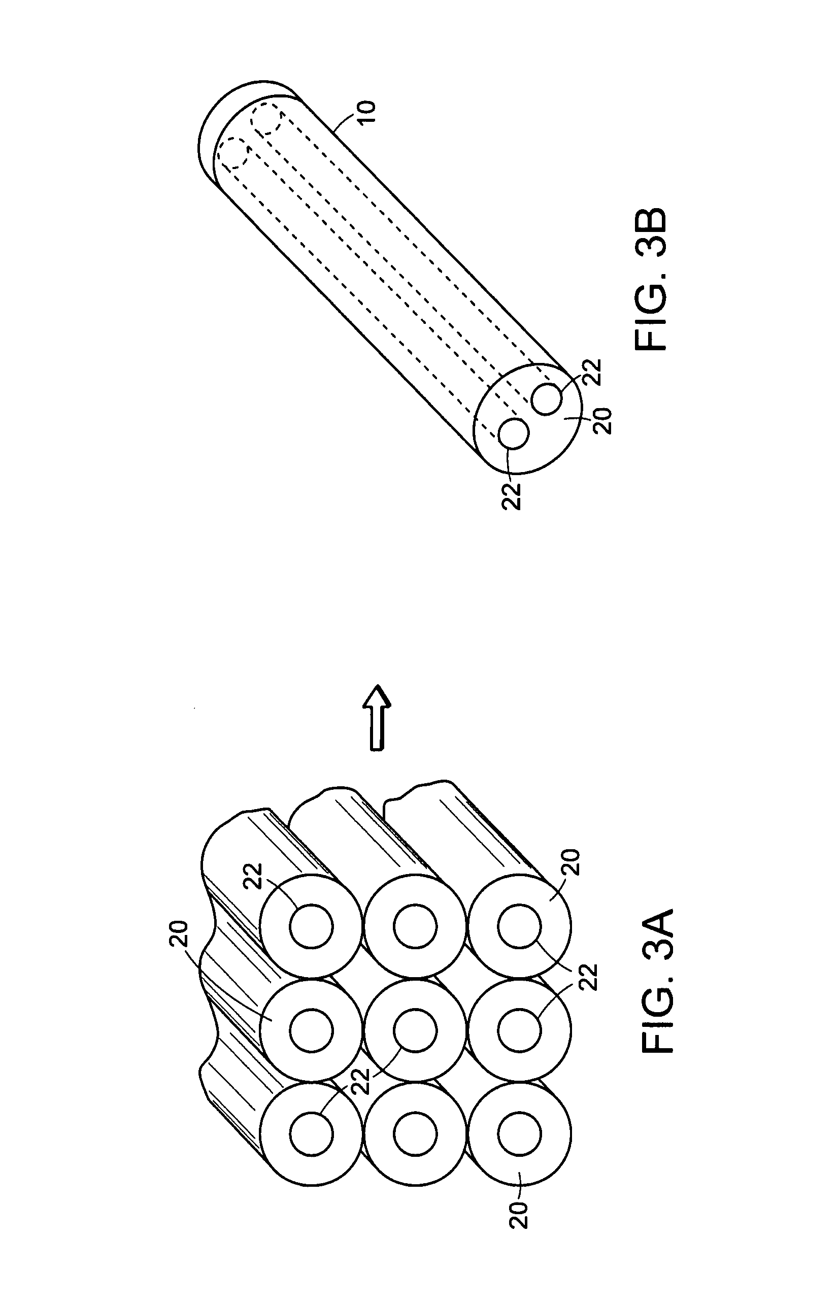
[0093] Powders of a conductive composition (30 vol % MoSi2, 20 vol % SiC, remainder Al2O3) and an insulating composition (20 vol % SiC and 80 vol % Al2O3) were separately mixed with about 16 wt % water and 5 wt % Methyl Cellulose (Dow A4M) to form two pastes. The two pastes are formed into rod shapes with the insulating paste forming about 40 rods elements and the resistive paste forming about 5 elements that are segregated by the insulating rods. Those packed rods are then extruded and reduced through a 0.31 inch diameter die on a Mohr piston extruder to provide a cylindrical heating element.

[0094] After that replication process, the conductive rods are reduced to about 0.05 inches in diameter and two of the conductive rods can form a circuit with a conductive cap affixed to the distal end of the heating element.

[0095] The ...

example 2

Co-Axial Heating Element

[0097] A heating element of corresponding to the configuration of FIG. 5 of the drawings is prepared by the general procedures of Example 1 above.


PUM

PropertyMeasurementUnit
voltageaaaaaaaaaa
voltageaaaaaaaaaa
voltageaaaaaaaaaa

Abstract

In one aspect, ceramic resistive heating elements are provided that comprise three or more electrically segregated conductive zones. In another aspect, ceramic heating elements are provided that comprise a plurality of conductive zones, wherein only a portion of the conductive zones pass current during use of the heating element. In a further aspect, heating elements of the invention can be readily modified to operate at a variety of voltages. The multiple conductive zones can provide extended heating element operating lifetimes.

Description

[0001] The present application clams the benefit of U.S. provisional application No. 60 / 799,218 filed May 9, 2006, which is incorporated by reference herein in its entirety.BACKGROUND [0002] 1. Field of the Invention [0003] In one aspect, the invention provides new ceramic resistive heating elements that comprise multiple conductive zones, particularly three or more conductive zones or pathways. In another aspect, ceramic heating elements are provided that comprise a plurality of conductive zones, wherein only a portion of the conductive zones pass current during use of the heating element. Preferred heating elements of the invention also can be readily modified to operate at a variety of voltages. [0004] 2. Background [0005] Ceramic materials have enjoyed great success as igniters in e.g. gas-fired furnaces, stoves and clothes dryers. Ceramic igniter production includes constructing an electrical circuit through a ceramic component a portion of which is highly resistive and rises i...

Claims


Application Information

Patent Timeline
Patent Type & Authority Applications(United States)
IPC IPC(8): H05B7/00F23Q7/00H05B7/16H05B1/00
CPCF27D99/0006H05B2203/027H05B2203/018H05B3/141F23Q7/22H05B3/00H01B1/18C03B37/04
Inventor WILLKENS, CRAIG A.
Owner COORSTEK INC
Why Eureka
Try Eureka