Waste blower for a paper sheet punching and embossing machine

Active Publication Date: 2007-12-27
MASTERWORK GROUP CO LTD
View PDF7 Cites 5 Cited by
  • Summary
  • Abstract
  • Description
  • Claims
  • Application Information

AI Technical Summary

Benefits of technology

[0009] To overcome the problems described above, preferred embodiments of the present invention provide a sheet punching and embossing machine in which a costly retrofitting of the machine is avoided, reliable ejection of different gripping margins is accomplished at maximum machine performance and with low cost and simple structural elements.
[0010] According to preferred embodiments of the present invention, a blower blows air towards an ejection station so that a directed current of air acts on the gripping margin. According to preferred embodiments of the present invention, a sheet punching and embossing machine achieves reliable ejecting of the gripping margin without any retrofitting of the grip opening cam. Thus, ejection of the gripping margin is achieved at low cost.
[0011] In a preferred embodiment of the present invention, several blowers are secured next to one another across the entire width of the ejection station, so that a blower strip is defined. This ensures that gripping margins of different sizes can be reliably ejected over the entire width of the ejection station.
[0012] Preferably, a conveyor belt is provided in the ejection station below the movement trajectory of the gripper car. This facilitates the ejection of especially large gripping margins.
[0013] In another preferred embodiment of the present invention, the blower is secured inside the circular path of the gripper car in the machine frame. This ensures that the current of air can be accurately directed towards the conveyor belt.
[0015] The use of a blower as a blowing and / or sucking blower produces a defined ejecting of the gripping margin because during the ejection of a long gripping margin, the air is transformed by the blower (either sucking or blowing) into a directed current of air. This enables a secure delivery of the gripping margin on a waste belt disposed beneath the path of the gripper car.

Problems solved by technology

Since an impression of the gripper on the final punched and / or embossed sheet is undesirable, the marginal region at which the gripper grabs the sheet is separated from the finished sheet.
Depending on the type of sheet being processed in the machine, a larger or smaller gripping margin will be wasted.
Especially in the case of a gripping margin equal to the size of the sheet, this results in retrofitting costs, on the one hand, and a reduction in the machine speed, on the other, in order to eject a gripping margin equal to the size of the sheet from the machine.

Method used


Image

  • Waste blower for a paper sheet punching and embossing machine
  • Waste blower for a paper sheet punching and embossing machine
  • Waste blower for a paper sheet punching and embossing machine

Examples


Embodiment Construction

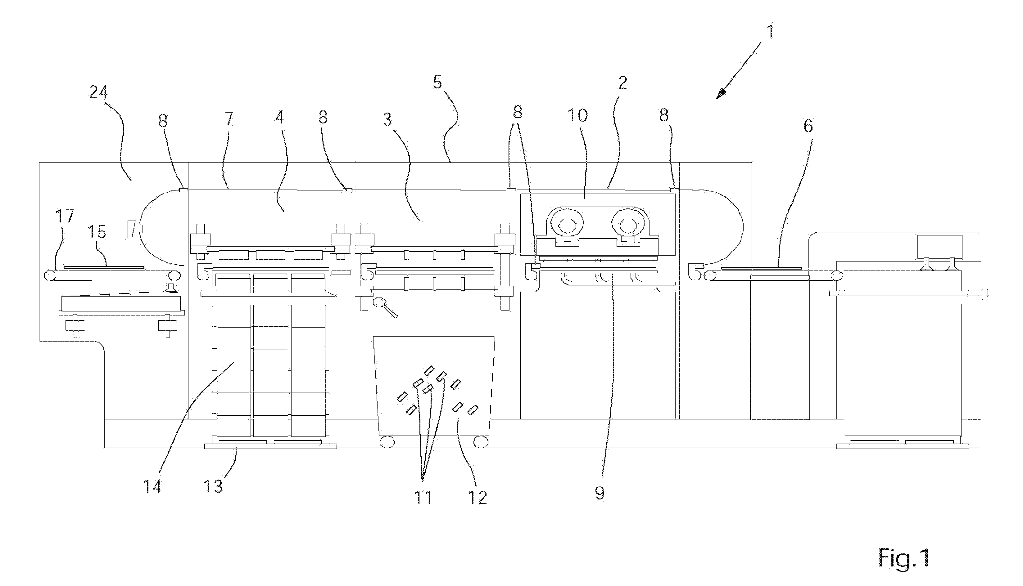
[0020]FIG. 1 shows the basic layout of a sheet punching and embossing machine 1 for punching, tearing off, embossing and delivery of sheets of paper, cardboard, or other stock materials. The punching and embossing machine 1 includes a punching mechanism 2, a tear-off mechanism 3, a delivery mechanism 4 and an ejection station 24, which are supported and enclosed in a common machine housing 5.

[0021] The sheets 6 are gripped in a gripping margin at their front edge by gripper rods 8 attached to revolving chains 7 and transported intermittently through the various stations 2, 3, 4 and 24 of the punching and embossing machine 1.

[0022] The punching station 2 includes a lower table 9 and an upper table 10. The lower table 9 is securely mounted in the machine frame and provided with a counterplate for the punching blade. The upper table 10 is mounted so as to be movable vertically up and down.

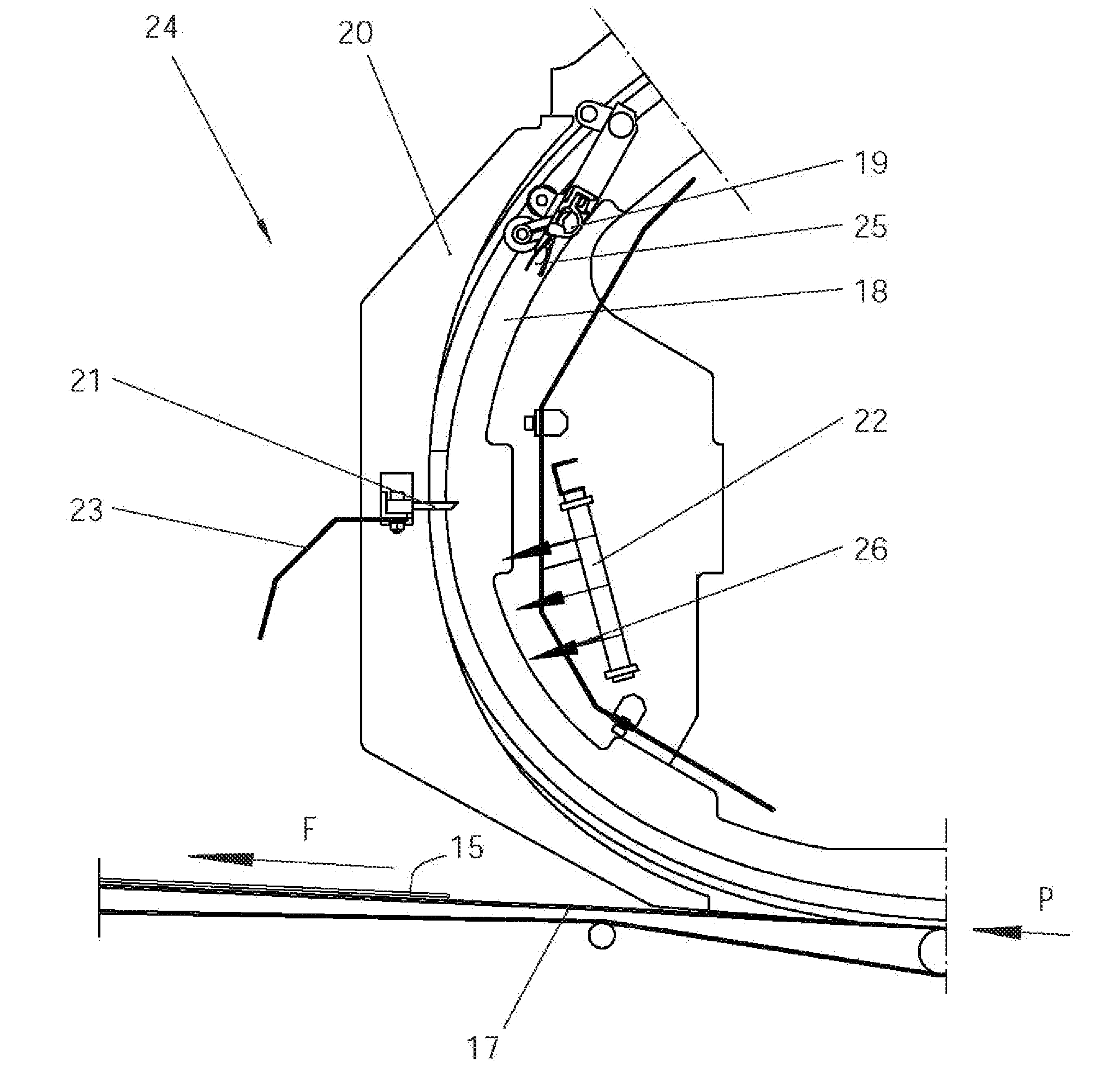
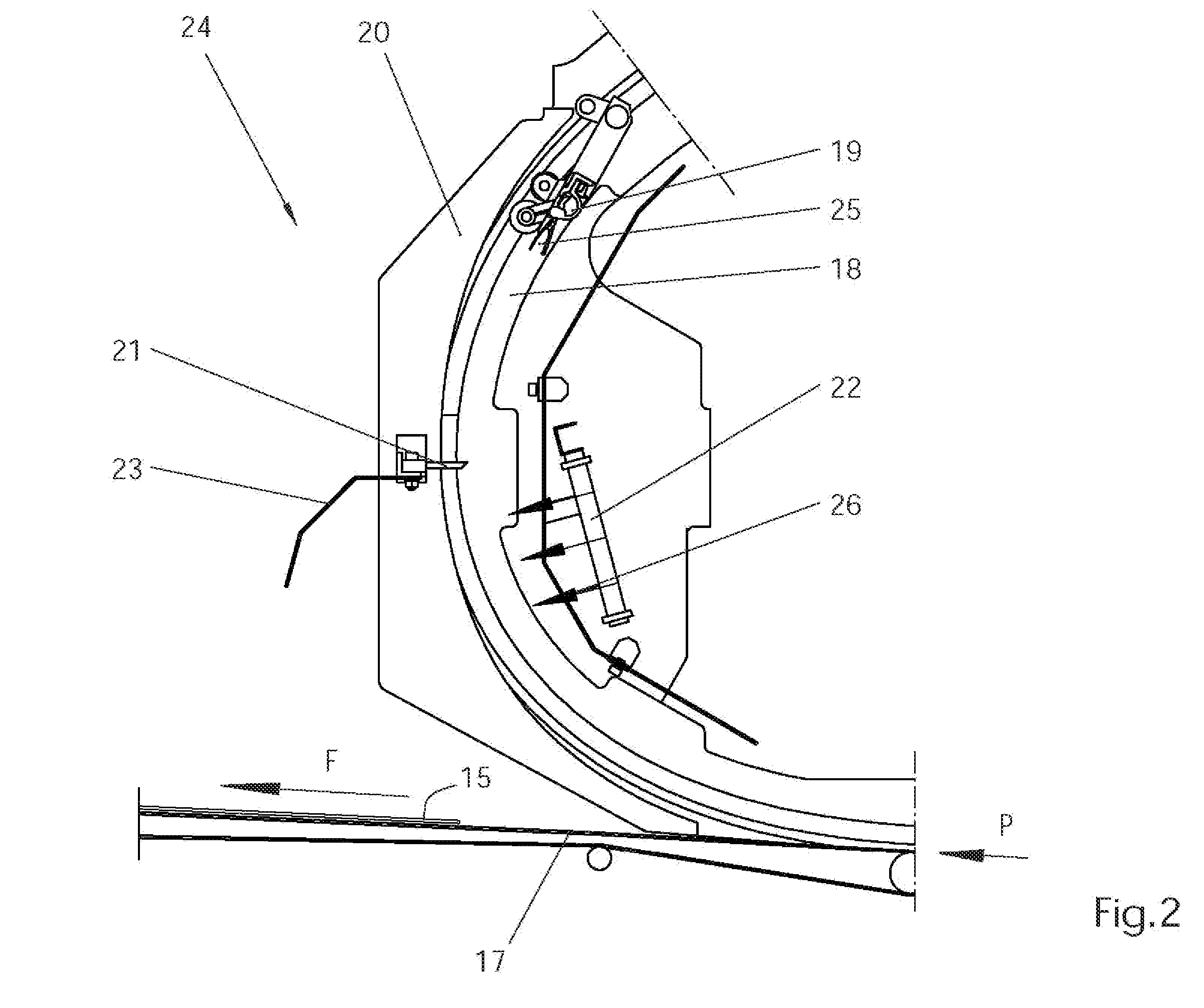
[0023] The gripper rod 8 transports the sheet 6 from the punching and embossing station 2 into ...


PUM

PropertyMeasurementUnit
Weightaaaaaaaaaa
Sizeaaaaaaaaaa
Speedaaaaaaaaaa

Abstract

A sheet punching and embossing machine includes revolving gripper cars with which a gripping margin of a sheet is grasped by grippers disposed on the gripper car so as to move the sheet through the machine, a punching station in which the gripping margin can be separated from the sheet, a delivery station in which the gripping margin can be further separated from the sheet, and an ejection station in which the gripping margin can be ejected from the gripper. The ejection station includes a blower which directs a current of air at the gripping margin.

Description

BACKGROUND OF THE INVENTION [0001] 1. Field of the Invention [0002] The present invention relates to a paper sheet punching and embossing machine. [0003] 2. Description of the Related Art [0004] In known sheet punching and embossing machines, which are used for punching, tearing off, embossing and delivery of sheets of paper, cardboard, and other stock materials, it is known how to move the sheets with gripper cars into the individual stations of the machine. Grippers are secured on the cars and grab the sheets at a front end, while the gripper cars are moved on endless chains through the machine. With this type of movement of the sheets through the machine, continuous operation in the individual stations of the machine arranged one after the other is obtained. Since an impression of the gripper on the final punched and / or embossed sheet is undesirable, the marginal region at which the gripper grabs the sheet is separated from the finished sheet. This gripping margin is usually disc...

Claims


Application Information

Patent Timeline
IPC IPC(8): B65H29/32
CPCB26D7/1818B26D7/1854B26D7/32B26F1/40B65H2801/42B65H5/085B65H29/042B65H2301/543B65H5/08B65H2701/176
Inventor LAPPOK, REINHARDPALMEN, PETERZANDERS, GUIDO
Owner MASTERWORK GROUP CO LTD
Why Eureka
Try Eureka