Display panel module and radio frequency identification module applied thereto

a radio frequency identification and display panel technology, applied in the field of display panels, can solve the problems of affecting the view area of the display panel, the installation of the antenna in the external portion of the display panel is not suitable, and the antenna cannot function after a rear cover, so as to achieve easy reading and improve production efficiency

Inactive Publication Date: 2007-12-27
CHUNGHWA PICTURE TUBES LTD
View PDF3 Cites 26 Cited by
  • Summary
  • Abstract
  • Description
  • Claims
  • Application Information

AI Technical Summary

Benefits of technology

[0007]Accordingly, the present invention is directed to a wireless radio frequency identification module, disposed on a display panel, thereby under a condition of not affecting the view area of the display panel, enabling a management for more production and easily maintaining each fabricating machine.
[0008]The present invention further relates to a liquid crystal display (LCD) panel in which an antenna is disposed on a surface of an outer plate and can transmit / receive all fabricating information regarding the LCD panel with improved convenience of production management of LCD panels and easier maintenance programs for fabricating machines.
[0016]The present invention utilizes the installation of the antenna of the radio frequency identification module on the LCD display panel for easily reading all the fabricating information during the production management, the subsequent maintenance of each fabricating machine and improvement of production efficiency.

Problems solved by technology

However, installation of antenna in the external portion of the display panel is not suitable; therefore, the antenna of the RFID system can be only disposed on the reverse surface of the display panel.
However, if the antenna is disposed on the reverse side of the display pane, the antenna fails to function after a rear cover assembled to the display panel.
Additionally, if the antenna is disposed on the obverse side of the display panel(i.e. the display side), the view area of the display panel will be affected.

Method used


Image

  • Display panel module and radio frequency identification module applied thereto
  • Display panel module and radio frequency identification module applied thereto

Examples


Embodiment Construction

[0021]Reference will now be made in detail to a decoding device for product code decoding and decoding method thereof, examples of which are illustrated in the accompanying drawings. Wherever possible, the same reference numbers are used in the drawings and the descriptions to refer to the same parts.

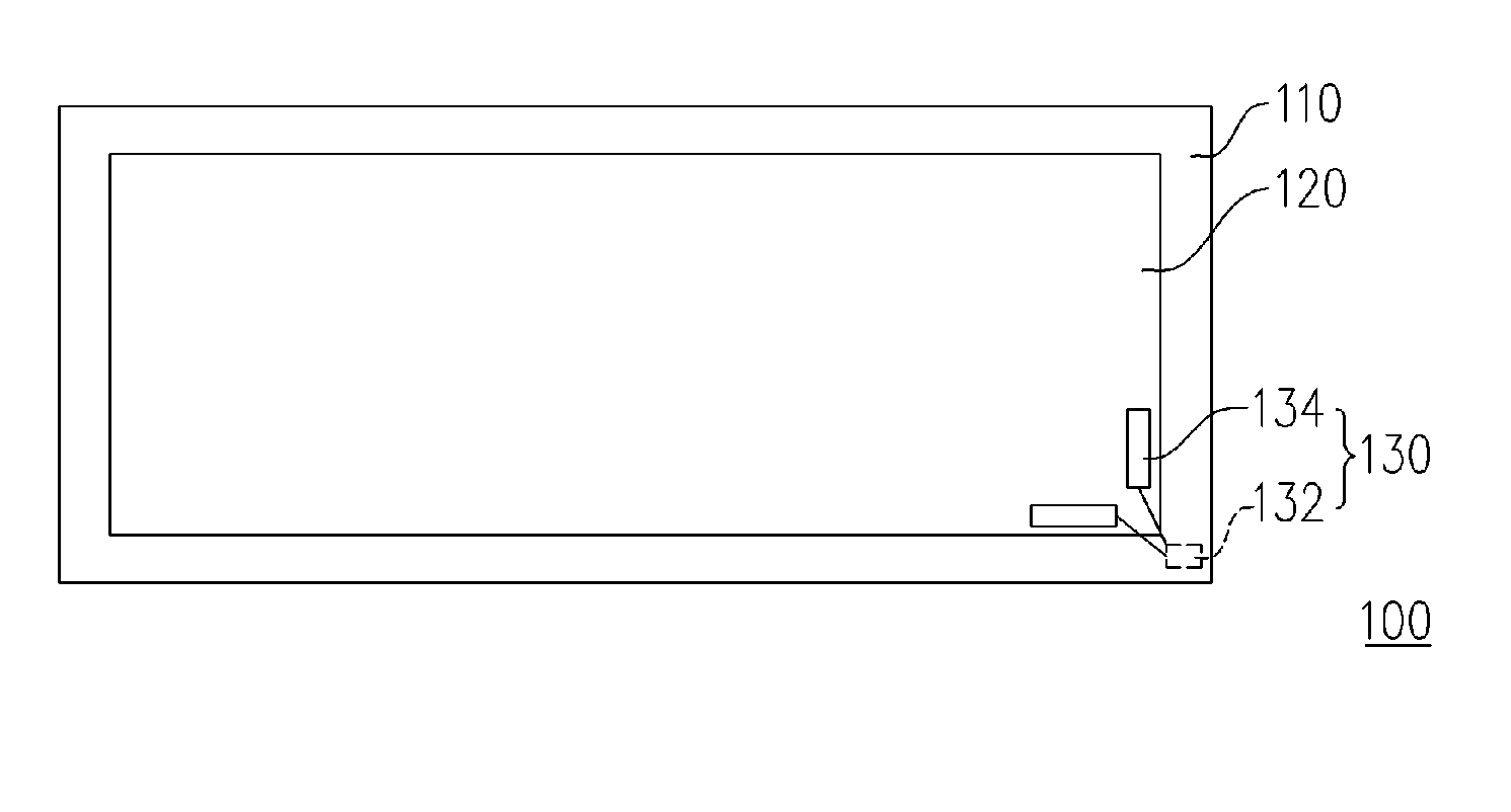
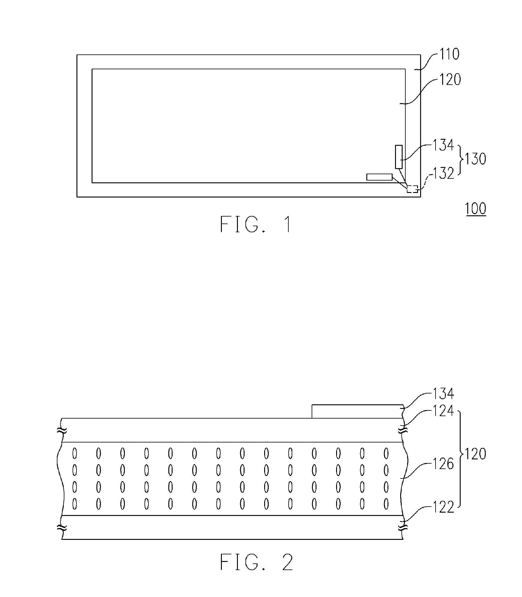
[0022]FIG. 1 schematically shows a top view of one LCD display panel module of one preferred embodiment of the present invention. FIG. 2 shows a cross sectional view of the LCD display panel module of one preferred embodiment of the present invention as shown in FIG. 1. Referring to FIGS. 1 and 2, a LCD display panel module 100 comprises an outer frame 110, an LCD display panel 120 and a radio frequency identification module 130 wherein the LCD display panel 120 comprises an active device array substrate 122, a color filter plate 124 and a liquid crystal layer 126. Additionally, the color filter plate 124 is upper to the active device array substrate 122, and the liquid crystal layer 12...


PUM


Abstract

A display panel module with a transparent radio frequency identification module is provided. The radio frequency identification module comprises a radio frequency identification chip and a transparent antenna electrically connected thereto. Since the antenna of the radio frequency identification module comprises transparent material, the antenna can be disposed on the surface of the display panel without views of the display panel being covered.

Description

BACKGROUND OF THE INVENTION[0001]1. Field of the Invention[0002]The present invention generally relates to a display panel, and more particularly to a display panel and a transparent radio frequency identification module applied thereto.[0003]2. Description of Related Art[0004]To conveniently control fabricating flow, quality and fabricating cost of a product, manufacturers have recently labeled the product with a bar code for identification and records of fabricating information including cost of raw material and quality of the product and fabricating specification, quality and the time for processing the product by each fabricating machine during the fabrication process. A database built for storing such information, which enables the operators of factory to only read the barcode of the product when controlling the fabricating flow of the product to easily search all fabricating information of the product. Accordingly, the factory operators can precisely calculate the fabrication ...

Claims


Application Information

Patent Timeline
Patent Type & Authority Applications(United States)
IPC IPC(8): G08B13/14
CPCG02F1/1303G02F2001/133354G06K19/07749G06K19/041G02F2001/133374G02F1/133374G02F1/133354
Inventor HUANG, CHI-FANGLIU, CHIA-LINMO, CHI-NENG
Owner CHUNGHWA PICTURE TUBES LTD
Why Eureka
Try Eureka