Direct Volume Rendering with Shading

a 3d image and volume rendering technology, applied in the field of data processing, can solve the problems of large processing power waste in homogeneous areas, limited knowledge of techniques, and large computation of overall contributions, and achieve the effects of improving user's perception, slow variation, and simplifying computations

Inactive Publication Date: 2007-12-27
KONINKLIJKE PHILIPS ELECTRONICS NV
View PDF2 Cites 11 Cited by
  • Summary
  • Abstract
  • Description
  • Claims
  • Application Information

AI Technical Summary

Benefits of technology

[0010] An advantage of the invention is to simplify computations in picture areas with low gradients where the information is similar and slowly varying. Homogenous areas are often areas that present the least interest to the final rendering and data within these areas is so slowly varying that replacing exact computation results with uniform value may not alter the final result and the user's overall perception of the display. Conversely, user's perception may be improved because the simplified contribution calculation of the invention will be less affected by noise than a more complex full calculation. The invention both improves the overall user perception of the display and at the same time reduces the computational complexity and thereby increases the display speed.
[0011] In another embodiment, an additional gradient-based criterion is introduced to smoothen the transition between samples located in what's referred to as homogenous areas and areas with high gradient values. Samples with high gradients are often found in the vicinity of boundary surfaces between objects or different materials. The gradient estimate is compared with a second threshold and if the estimate value lies between the first and the second threshold, the contribution is set to a combination of the light model function derived for the exact gradient value and the previous contribution uniform value.
[0012] The invention also relates to a corresponding device and corresponding record carrier storing instructions for performing same.
[0013] These and other aspects of the invention will be apparent from and will be elucidated with reference to the embodiments described hereinafter.

Problems solved by technology

Other techniques exist to generate 2D images, e.g. maximum intensity projection, slicing, iso-surface visualization but these known techniques are limited in that only some of the 3D data values contribute to the final 2D result.
Computation of the overall contributions can be rather heavy for large 3D data sets and much processing power may be wasted for homogeneous areas.
In addition, noise in the homogeneous areas may cause undesired disturbing patterns, which may lead to a blurring of the image.
This alters the optical appearance of these areas, however, in order to perform such rendering, the gradient still had to be calculated for every sample location in the volume data set.

Method used


Image

  • Direct Volume Rendering with Shading
  • Direct Volume Rendering with Shading
  • Direct Volume Rendering with Shading

Examples


Embodiment Construction

[0020] The invention will be described in the context of medical images however one should not limit the scope of the invention to medical applications. The invention clearly encompasses any type of application, which uses the features of the invention, though in remote technical fields where 3D arrays of data are used. For example, the invention would be beneficial to other field like video gaming, meteorology and aeronautic, etc . . .

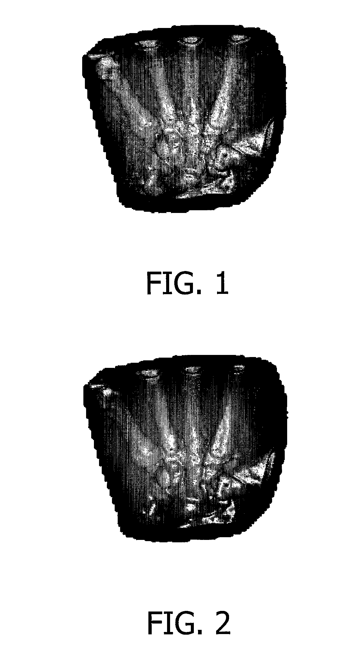
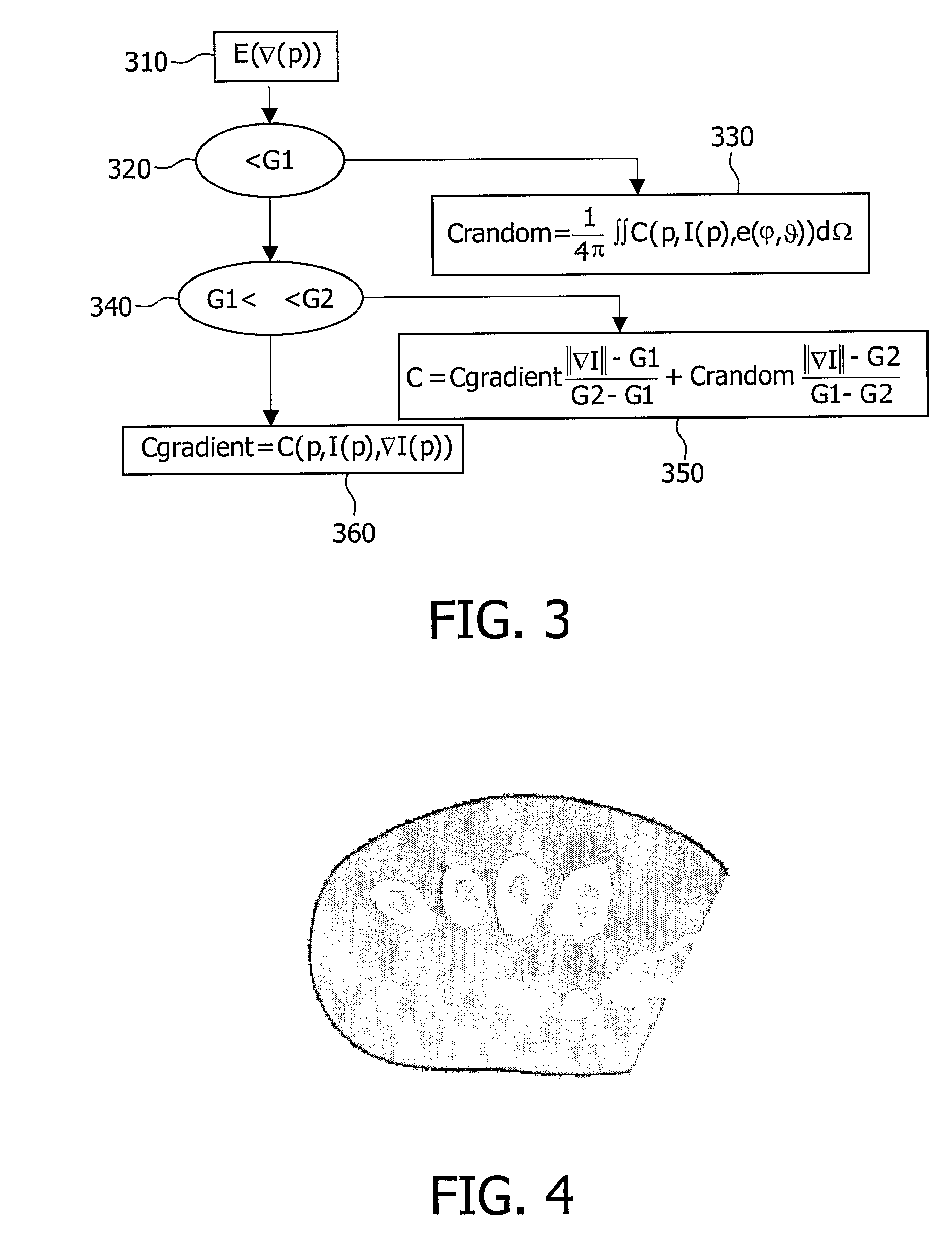
[0021]FIG. 1 and FIG. 2 represent displays of the internal bone structure of a human hand. The two displays show the fingers' bones skeleton, and the hand's tissue shows up as dark homogenous areas. Homogenous areas are referred as such in contrast with areas where the body structure changes (e.g. bone surfaces boundaries). Both images are based on the same original set of data, obtained for example by X-ray radiation of the person's hand but this original set of data is handled in two different manners and consequently, the displays differ in qualit...


PUM


Abstract

The present invention relates to direct volume rendering based on a light model applied to a 3D array of information data samples. Gradients are first estimated for the individuals samples, and a simple shading is done on the samples with low gradient, i.e. homogenous areas.

Description

FIELD OF THE INVENTION [0001] The present invention relates to data processing. The invention is particularly pertinent to direct volume rendering and visualization of 3D images in the medical domain. BACKGROUND OF THE INVENTION [0002] Direct Volume Rendering (DVR) is a direct method of obtaining two-dimensional images of a three-dimensional data set. Other techniques exist to generate 2D images, e.g. maximum intensity projection, slicing, iso-surface visualization but these known techniques are limited in that only some of the 3D data values contribute to the final 2D result. In direct volume rendering, the whole set of data has the potential to contribute to the 2D output image. Direct volume rendering thus provides a projection of the volume into the display window and although there may be ambiguity as to the depth of some regions of visualization, interactivity allows the user to manipulate the viewpoint and viewing angle and get a better feel of the viewed object and its volum...

Claims


Application Information

Patent Timeline
Patent Type & Authority Applications(United States)
IPC IPC(8): G06F7/60G06T15/06G06T15/40
CPCG06T15/40G06T15/06
Inventor WEESE, JUERGENKIEFER, GUNDOLFBUSCH, MARCLEHMANN, HELKO
Owner KONINKLIJKE PHILIPS ELECTRONICS NV
Why Eureka
Try Eureka