
Method of distortion correction in shrink processes for fabrication of write poles

a write pole and shrink process technology, applied in the manufacture of head surfaces, manufacturing tools, instruments, etc., can solve the problems of increasing write and read errors, increasing the chance of interference from adjacent tracks, and increasing the risk of affecting so as to improve the overall performance of the disk drive, improve the manufacturing yield of the write pole, and correct the distortion of the photo resist.

Inactive Publication Date: 2008-01-03
WESTERN DIGITAL TECH INC
View PDF9 Cites 0 Cited by
  • Summary
  • Abstract
  • Description
  • Claims
  • Application Information

AI Technical Summary

Benefits of technology

[0017]It is an advantage of the present invention that distortions in the photoresist can be corrected and thus P2 pole tips can be produced which also have these distortions corrected.
[0018]It is another advantage of the present invention that manufacturing yields for write heads are improved.
[0019]It is a further advantage of the present invention that overall performance of the disk drive is improved by utilizing write heads with corrected geometry.
[0020]It is yet another advantage of the present invention that write poles can be produced with flare points that are positioned within an acceptable range so that magnetic flux is channeled appropriately for good writing and re-writing performance.

Problems solved by technology

As the areal data storage density of magnetic media steadily increases and track widths become narrower and closer together, there is more and more chance of interference from adjacent tracks.
This interference naturally increases write and read errors, and is therefore undesirable.
As track widths become narrower, this balance becomes ever more delicate.
These acids make part of the RELACS material non-soluble in water, and thus not removable from the channel.
Other geometric factors will also be affected by the distortions in the expanded photoresist that may cause problems in the operation of the write head and thus of the disk drive as a whole.

Method used


Image

  • Method of distortion correction in shrink processes for fabrication of write poles
  • Method of distortion correction in shrink processes for fabrication of write poles
  • Method of distortion correction in shrink processes for fabrication of write poles

Examples


Embodiment Construction

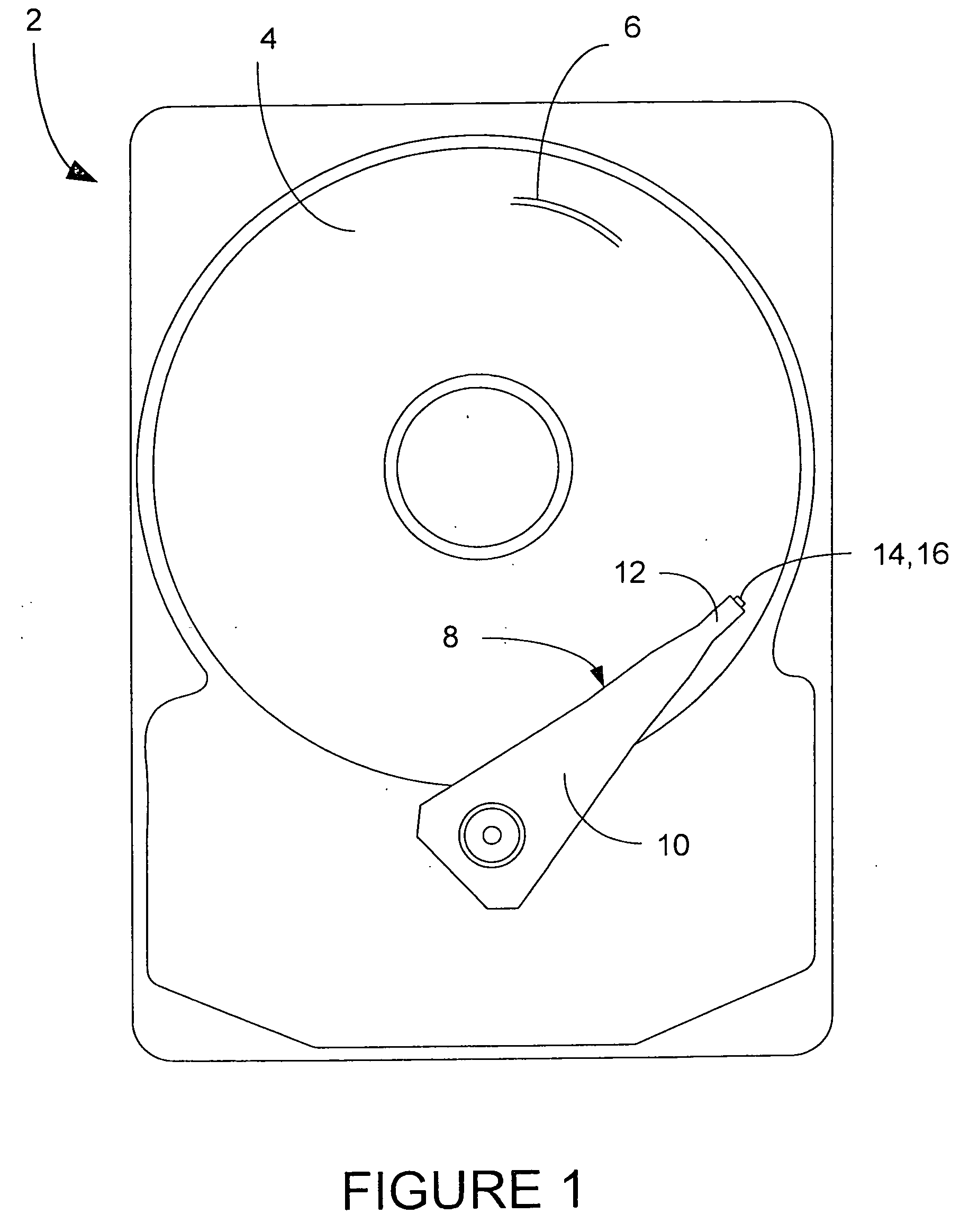
[0036]A magnetic disk drive 2 is shown generally in FIG. 1, having one or more magnetic data storage disks 4, with data tracks 6 which are written and read by a data read / write device 8. The data read / write device 8 includes an actuator arm 10, and a suspension 12 which supports one or more magnetic heads 14 included in one or more sliders 16.

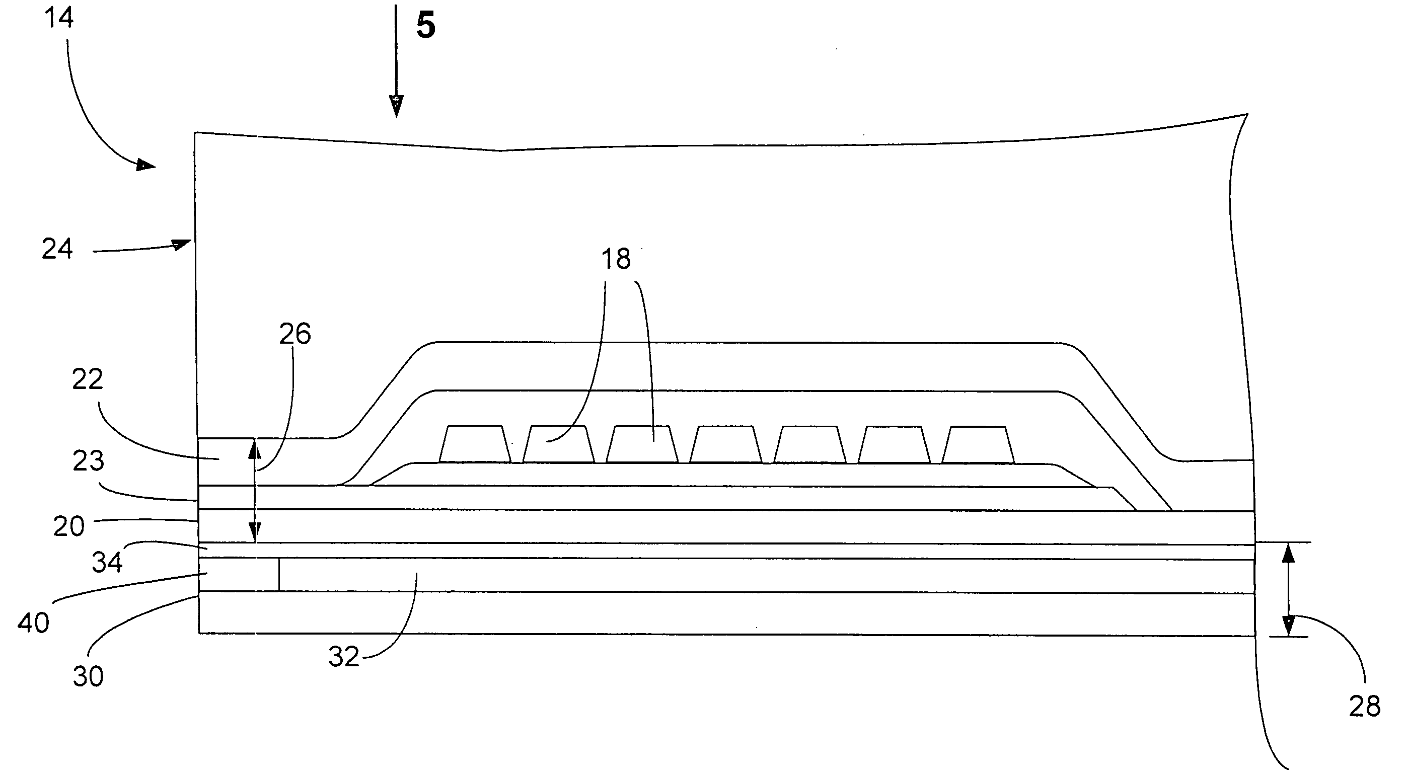
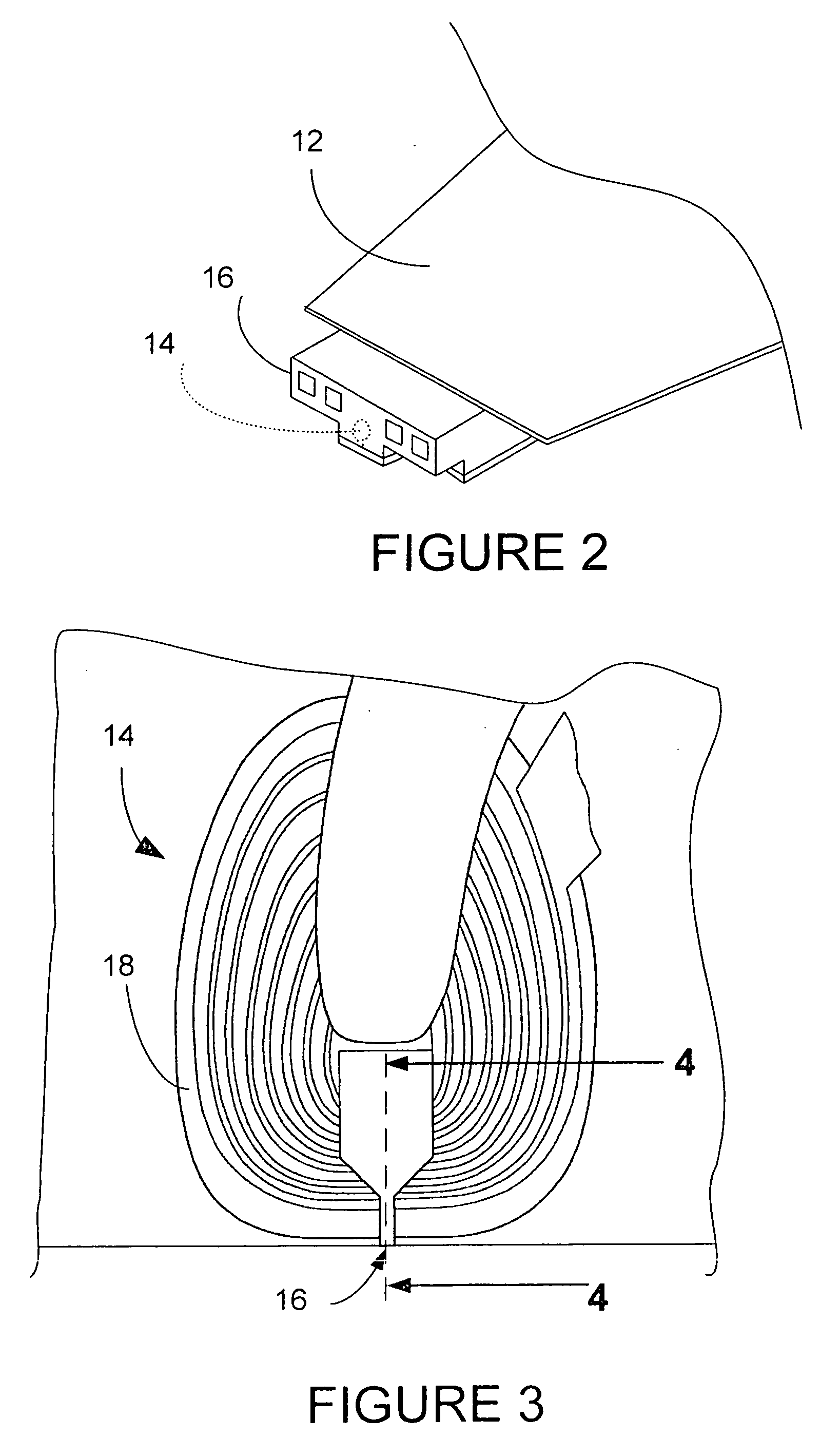
[0037]FIG. 2 shows a slider 16 in more detail being supported by suspension 12. The magnetic head 14 is shown in dashed lines, and in more detail in FIGS. 3 and 4. The magnetic head 14 depicted in FIGS. 3 and 4 include an induction coil 18, P1 pole 20, and a second pole P222 which is separated from P1 pole 20 by write gap 23. The P1 pole 20, second pole P222 and write gap 23 can be considered together to be included in the write head 26.

[0038]A read sensor 40 is sandwiched between a first magnetic shield, designated as S130 and a second magnetic shield S234, and these elements together make up the read head 28. An insulation layer 32 also separ...


PUM

PropertyMeasurementUnit
temperatureaaaaaaaaaa
angleaaaaaaaaaa
widthaaaaaaaaaa

Abstract

A method is presented for fabricating a write pole for a magnetic recording head, wherein a photoresist layer is formed on a wafer stack. A target P2 pole configuration is provided, and a photomask having a pattern is produced, and the pattern is transferred to the photoresist to create a patterned photoresist having at least one photoresist channel. A layer of photoresist channel shrinking film used to produce a reduced width photoresist channel in an expanded photoresist. A P2 pole tip is formed within the reduced width photoresist channel. The P2 pole tip is then compared to the target P2 pole configuration to identify distortions, which are then used to produce a distortion-corrected photomask. The distortion-corrected photomask is then used to produce a distortion-corrected expanded photoresist, which is then used to produce a distortion-corrected P2 pole tip.

Description

BACKGROUND OF THE INVENTION[0001]1. Field of the Invention[0002]The present invention relates generally to manufacture of heads for data storage devices and more specifically to a write head for a hard disk drive.[0003]2. Description of the Prior Art[0004]As the areal data storage density of magnetic media steadily increases and track widths become narrower and closer together, there is more and more chance of interference from adjacent tracks. This interference has become so common that the acronym “ATI” for Adjacent Track Interference has been coined. This interference naturally increases write and read errors, and is therefore undesirable. The design of write heads in general is a balance between producing poles which are narrow enough to prevent ATI and having poles broad enough to allow adequate magnetic flux flow to write or overwrite data satisfactorily. As track widths become narrower, this balance becomes ever more delicate. In an effort to produce more narrow pole tips, ch...

Claims


Application Information

Patent Timeline
Patent Type & Authority Applications(United States)
IPC IPC(8): G11B5/127
CPCG11B5/3116G11B5/3163Y10T29/49041Y10T29/49039Y10T29/49043Y10T29/49046Y10T29/49048Y10T29/49021Y10T29/49052
Inventor LEE, KIM Y.LO, JYH-SHURY
Owner WESTERN DIGITAL TECH INC
Learn More