Downhole flow-back control for oil and gas wells by controlling fluid entry

a technology of oil and gas wells and fluid entry, applied in the direction of fluid removal, earth drilling and mining, borehole/well accessories, etc., can solve the problems of both downhole and surface facilities, the operator cannot afford the cost of many of the most effective available treatment methods, and the flow-back of these grains during production can also be a problem, so as to achieve the effect of effectively controlling the flow-back control of downhol

Inactive Publication Date: 2008-01-03
HALLIBURTON ENERGY SERVICES INC
View PDF43 Cites 36 Cited by
  • Summary
  • Abstract
  • Description
  • Claims
  • Application Information

AI Technical Summary

Benefits of technology

[0012] The present invention relates generally to a method and apparatus utilized in hydrocarbon exploration. More specifically, the present invention rel...

Problems solved by technology

For many oil and/or gas wells, there are problems related to the inflow of various solids into the wellbore from the formation.
Other problem cases involve the flow-back of granular solids that have been pumped into the formation by some treatment process, such as proppant placed during a hydraulic fracturing treatment.
Flow-back of these grains during production can also be a problem.
In some of these cases, as well as in many other reservoirs, there can be both downhole and surface facility problems resulting from the flow-back of either formation solids or solids that were placed downhole during a pumping operation, such as during a hydraulic fracturing process, a frac-pack operation, a gravel pack completion, and the like.
One of the recurring problems with conventional technologies is that an operator cannot afford the cost of many of the most effective available treatment methods.
In many conventional well completions, particularly those using shape-charge perforating techniques and/or open-hole hydraulic fracturing methods, the operator does not have substantially complete control over where a pumped fluid is entering the reservoir (i.e., exiting the wellbore) at substantially all times during an injection operation.
Additionally, there is seldom a cost-effective method for controlled injection of such a treatment and/or chemi...

Method used


Image

  • Downhole flow-back control for oil and gas wells by controlling fluid entry
  • Downhole flow-back control for oil and gas wells by controlling fluid entry
  • Downhole flow-back control for oil and gas wells by controlling fluid entry

Examples


Embodiment Construction

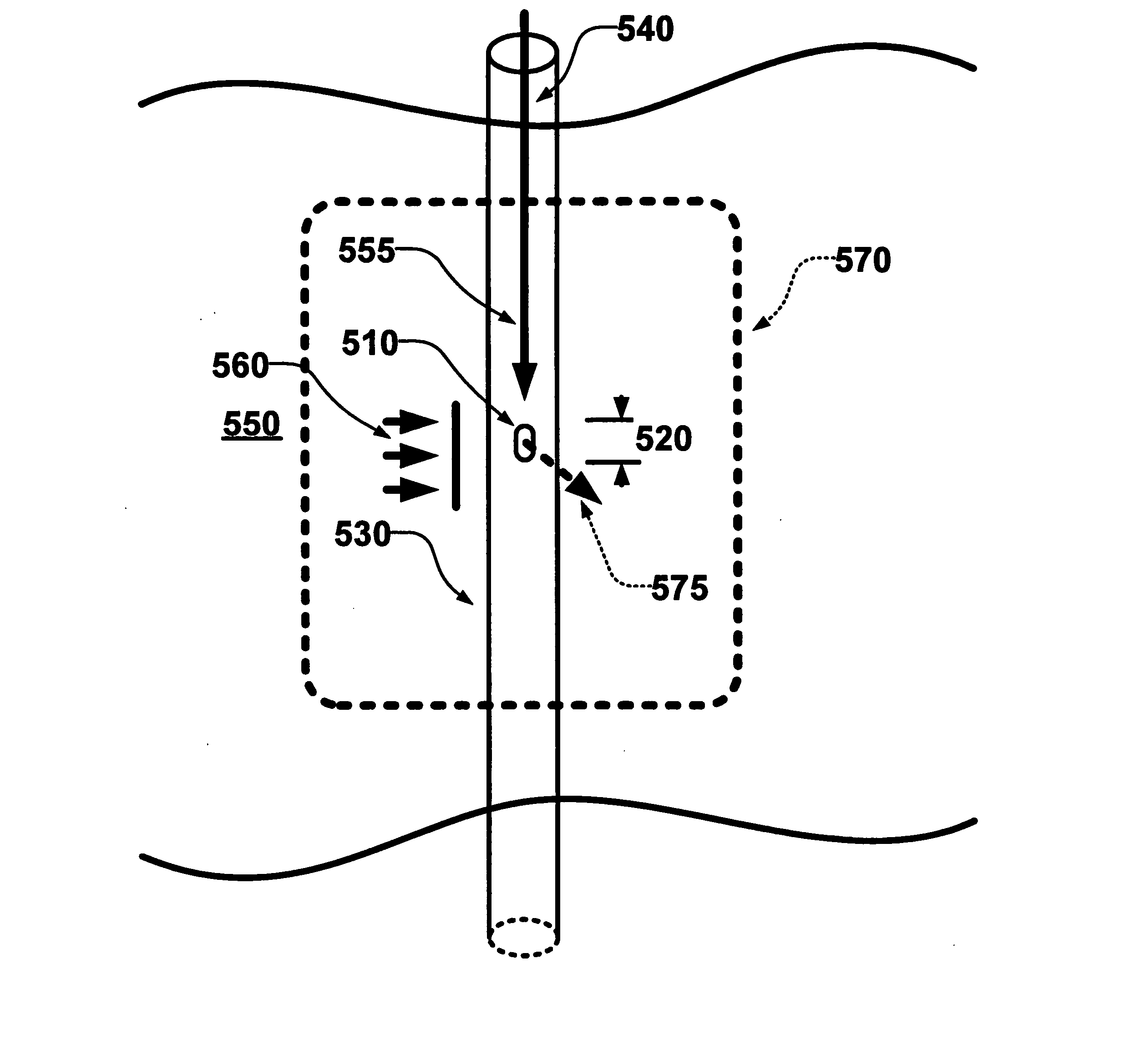
[0032] The present invention relates generally to a method and apparatus utilized in hydrocarbon exploration. More specifically, the present invention relates to a method and apparatus for improving downhole flow-back control of solids in oil and / or gas wells by controlling fluid entry into the wellbore.

[0033] Illustrative embodiments of the present invention are described in detail below. In the interest of clarity, not all features of an actual implementation are described in this specification. It will of course be appreciated that in the development of any such actual embodiment, numerous implementation-specific decisions must be made to achieve the developers' specific goals, such as compliance with system-related and business-related constraints, which will vary from one implementation to another. Moreover, it will be appreciated that such a development effort might be complex and time-consuming, but would nevertheless be a routine undertaking for those of ordinary skill in t...


PUM


Abstract

A method and apparatus for use in hydrocarbon exploration. The method and apparatus improve downhole flow back control in oil and/or gas wells by controlling fluid entry into the well bore. Either a single limited entry opening or a small cluster of limited entry openings is provided in a well liner or casing and cement sheath allowing fluid communication between a region of a well bore and a subterranean reservoir. The method also uses the limited entry opening or the cluster during an injection treatment of the subterranean reservoir to control fluid entry. The method also provides a proppant flow back treatment following the injection treatment of the subterranean reservoir.

Description

FIELD OF THE INVENTION [0001] The present invention relates generally to a method and apparatus utilized in hydrocarbon exploration. More specifically, the present invention relates to a method and apparatus for improving downhole flow-back control in oil and / or gas wells by controlling fluid exiting the wellbore during injection of a treatment fluid and entering the wellbore during treating fluid clean-up or production of reservoir fluids. BACKGROUND OF THE INVENTION [0002] For many oil and / or gas wells, there are problems related to the inflow of various solids into the wellbore from the formation. In some cases, formation particles are being transported into the wellbore by the inflow of the reservoir fluid and / or fluids and / or gases. The transportation of formation particles into the wellbore is particularly likely if the formation rock particles are not well cemented together and / or if the pressure differential between the wellbore pressure and the reservoir pressure becomes re...

Claims


Application Information

Patent Timeline
IPC IPC(8): E21B43/04E21B43/267
CPCE21B43/26E21B43/12
Inventor MCDANIEL, BILLY W.SURJAATMADJA, JIM B.
Owner HALLIBURTON ENERGY SERVICES INC
Why Eureka
Try Eureka