Ultrasonic Motor

a technology of ultrasonic motors and cylinders, applied in piezoelectric/electrostrictive/magnetostrictive devices, piezoelectric/electrostriction/magnetostriction machines, electrical equipment, etc., can solve the problems of unneeded preload springs and inability to work in liquid environments

Inactive Publication Date: 2008-01-03
MORIYA TADASHI +1
View PDF7 Cites 6 Cited by
  • Summary
  • Abstract
  • Description
  • Claims
  • Application Information

AI Technical Summary

Benefits of technology

[0019] The invented motor operates as a transmission type ultrasonic motor. The motor uses a coiled waveguide in the shape of a helical coil as a stator. The use of a coiled stator enables driving the rotor in a wide range of interfaces between the rotor and the stator. Therefore, the rotor can be driven with a small preload, making a preload spring unnecessary.

Problems solved by technology

(b) The conventional traveling wave type ultrasonic motor cannot work in a liquid environment unless appropriate waterproofing is provided.
Therefore, the rotor can be driven with a small preload, making a preload spring unnecessary.

Method used


Image

  • Ultrasonic Motor
  • Ultrasonic Motor
  • Ultrasonic Motor

Examples


example 1

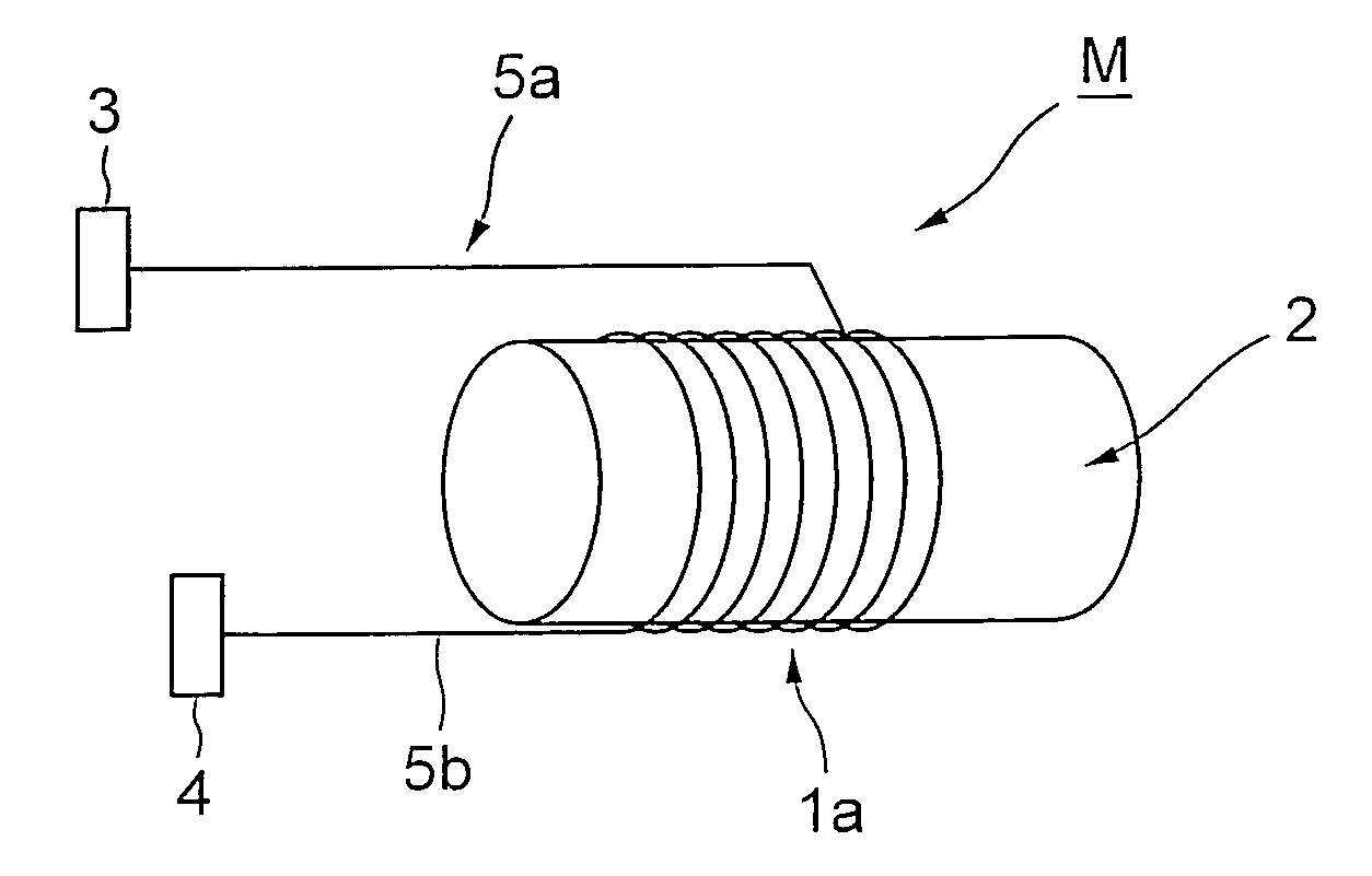
[0060]FIG. 5 shows the principle of example 1 of the invented traveling wave type ultrasonic motor that uses a coiled waveguide as a stator. The motor consists of transducers 3 and 4, waveguides 5a and 5b, a rotor 2, and a coiled acoustic waveguide 1a wound around the rotor 2.

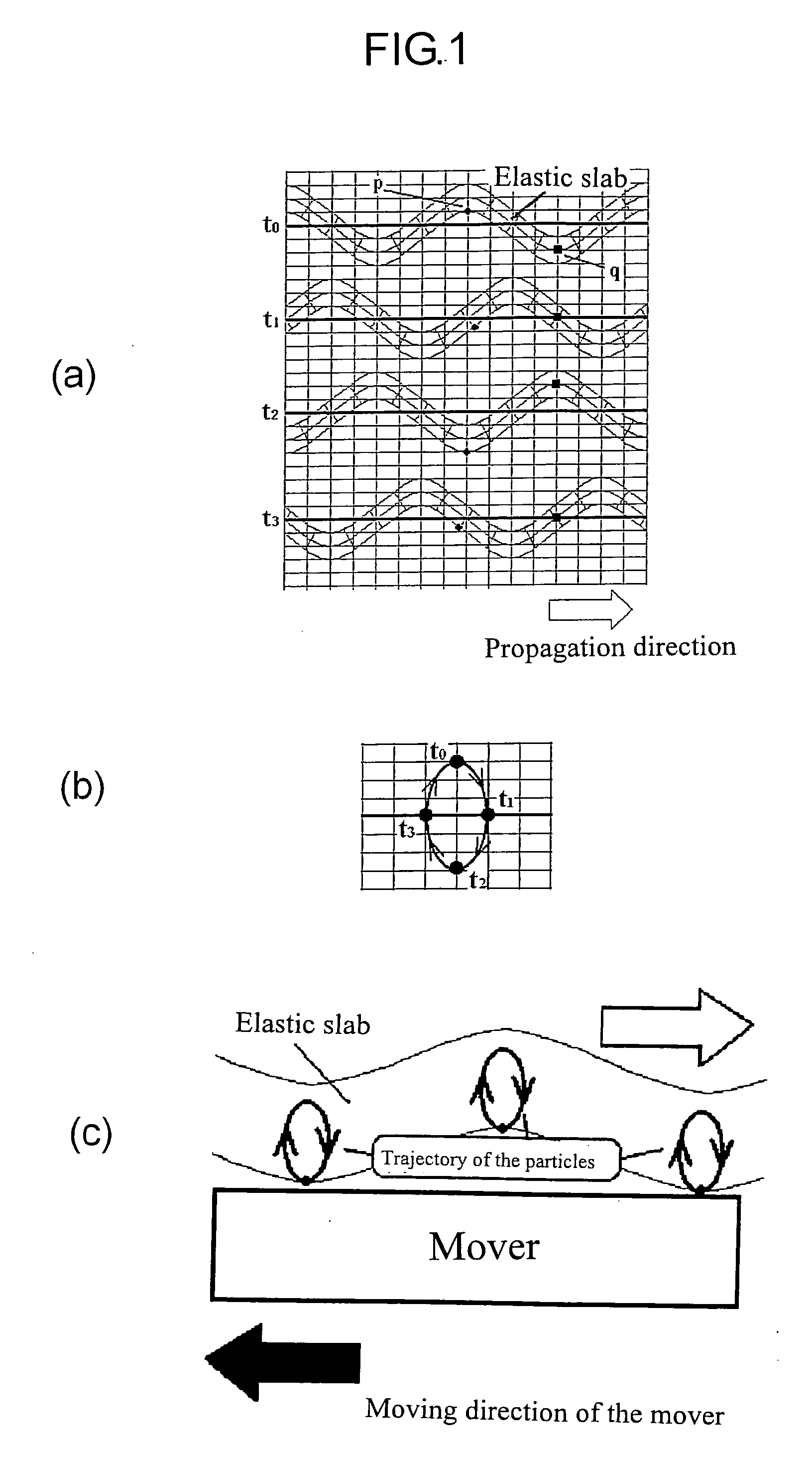
[0061] When an electric voltage is applied to the transducer 3, the flexural wave is excited, and is propagated along the waveguide 5a to the coiled acoustic waveguide 1a. The propagation of the flexural wave along the coiled acoustic waveguide causes an elliptical orbit of the point on the contact surface of the waveguide. The elliptical motion of the points causes the rotor to rotate in the direction opposite to that of the propagation of the flexural wave via the frictional force between the coiled acoustic waveguide and the rotor. Here every point on the waveguide in the contact region causes a driving force in the same direction. The flexural wave is attenuated as it propagates along the coiled waveguide....

example 2

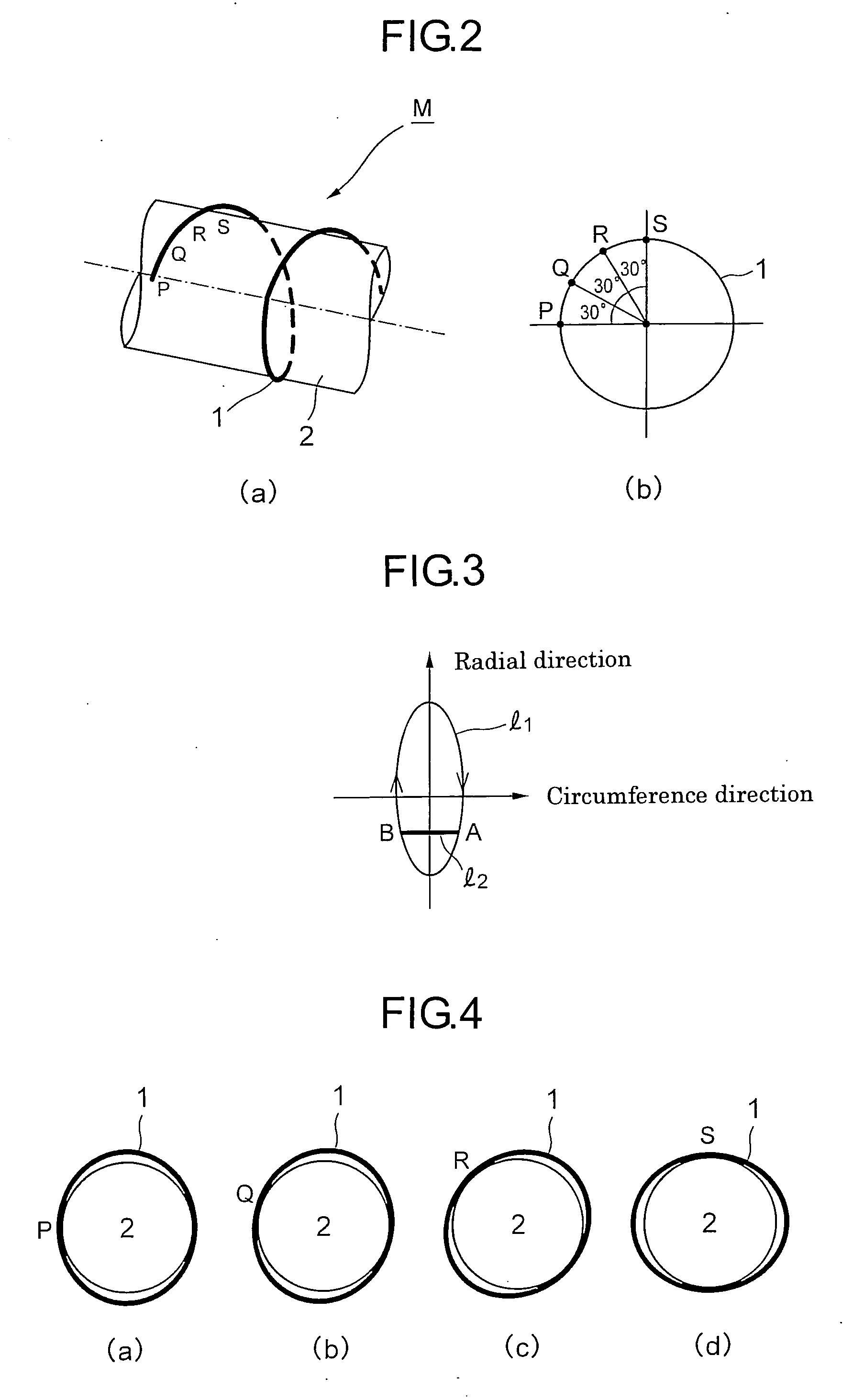
[0067] An example of the invented motor is shown in FIG. 7. The motor M consists of paired waveguides 5a and 5b, a rotor 2, a stator la placed inside the rotor 2, transducers 3 and 4. In this example, an electric voltage is applied to the transducer 3, and the flexural wave propagates along the waveguide 5a to the stator 1a. The elliptical movement of the surface element of the stator 1a causes the rotor to rotate as described in Example 1. FIG. 8 shows the enlarged arrangement of the stator 1a and the rotor 2.

[0068] The stator 1 can also be placed outside the rotor 2 as shown in FIG. 9.

[0069] The rotation speed and the torque of the motor depend on the diameters of the acoustic waveguide and the rotor, the amplitude of the flexural wave, and the duration of the pulse if the flexural wave is pulse modulated. Furthermore, a groove on the surface of the rotor modifies the torque and the rotation speed.

[0070] A motor based on the FIG. 8 was constructed. In this case, only one wavegu...

example 3

[0072]FIG. 10(a) is a diagram describing how an axial symmetric body such as a sphere can be rotated by using a coiled waveguide wound around in close external contact with the sphere as shown. FIG. 10(b) is a diagram showing that a hollow tube 2 placed in close internal contact with the coil 1 can be moved linearly along the axis of the coil.


PUM


Abstract

The present invention relates to an ultrasonic motor comprising a stator formed by using an acoustic waveguide of helical coil shape or an acoustic waveguide of in-plane spiral coil shape, so that a rotor placed in close proximity to, or in close contact with the coil is rotated, traveled, or performed curved line movement by the propagation of the wave on the stator, thereby eliminating the provision of a preload spring and an absorber, simplifying the structure of the motor, reducing the size of the motor, and enabling to work in a liquid environment without water proofing and rotation of a hollow tube.

Description

TECHNICAL FIELD [0001] The present invention relates to an ultrasonic motor that uses a stator in the form of a coil for use in the fields of medicine and industry. BACKGROUND ART [0002] Ultrasonic motors or actuators find many applications in the field of mechanical engineering such as in robotics, electric motors, in the field of medicine such as diagnosis and therapy, and in the field of measurements that must be free from electro magnetic interference. The motors for use in medicine such as in intravascular ultrasound (IVUS) and thrombectomy require the following characteristics, because the motors are used inside a vessel: [0003] (a) The motor must be as small as possible, typically 1 mm in diameter and 5 mm in length. [0004] (b) The motor should work in a liquid environment. [0005] (c) The rotor should be a hollow tube. [0006] Conventional motors can be evaluated as follows from the viewpoint of said requirements: [0007] Traveling wave type ultrasonic motors are widely used in...

Claims


Application Information

Patent Timeline
Patent Type & Authority Applications(United States)
IPC IPC(8): H02N2/16H02N2/12H01L41/09H02N2/00
CPCH02N2/16H02N2/08B82Y40/00H02N2/00
Inventor MORIYA, TADASHIFURUKAWA, YUJI
Owner MORIYA TADASHI
Why Eureka
Try Eureka