Motor control device
a technology of motor control and control device, which is applied in the direction of motor/generator/converter stopper, electronic commutator, dynamo-electric converter control, etc., can solve the problems of inability to perform motor control as desired, difficulty in accurately estimating the position and speed of the rotor in low-speed rotation or at a standstill, and inability to switch within a single coordinate system. not always the optimum choi
- Summary
- Abstract
- Description
- Claims
- Application Information
AI Technical Summary
Benefits of technology
Problems solved by technology
Method used
Image
Examples
first embodiment
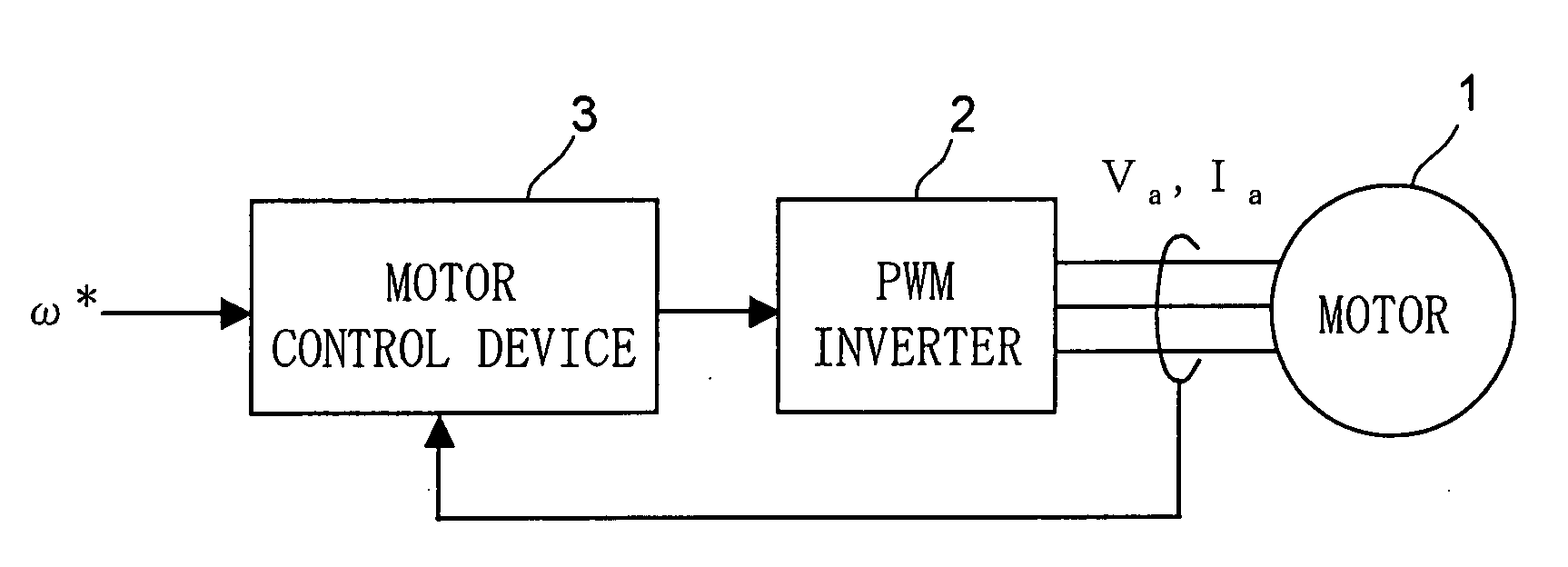
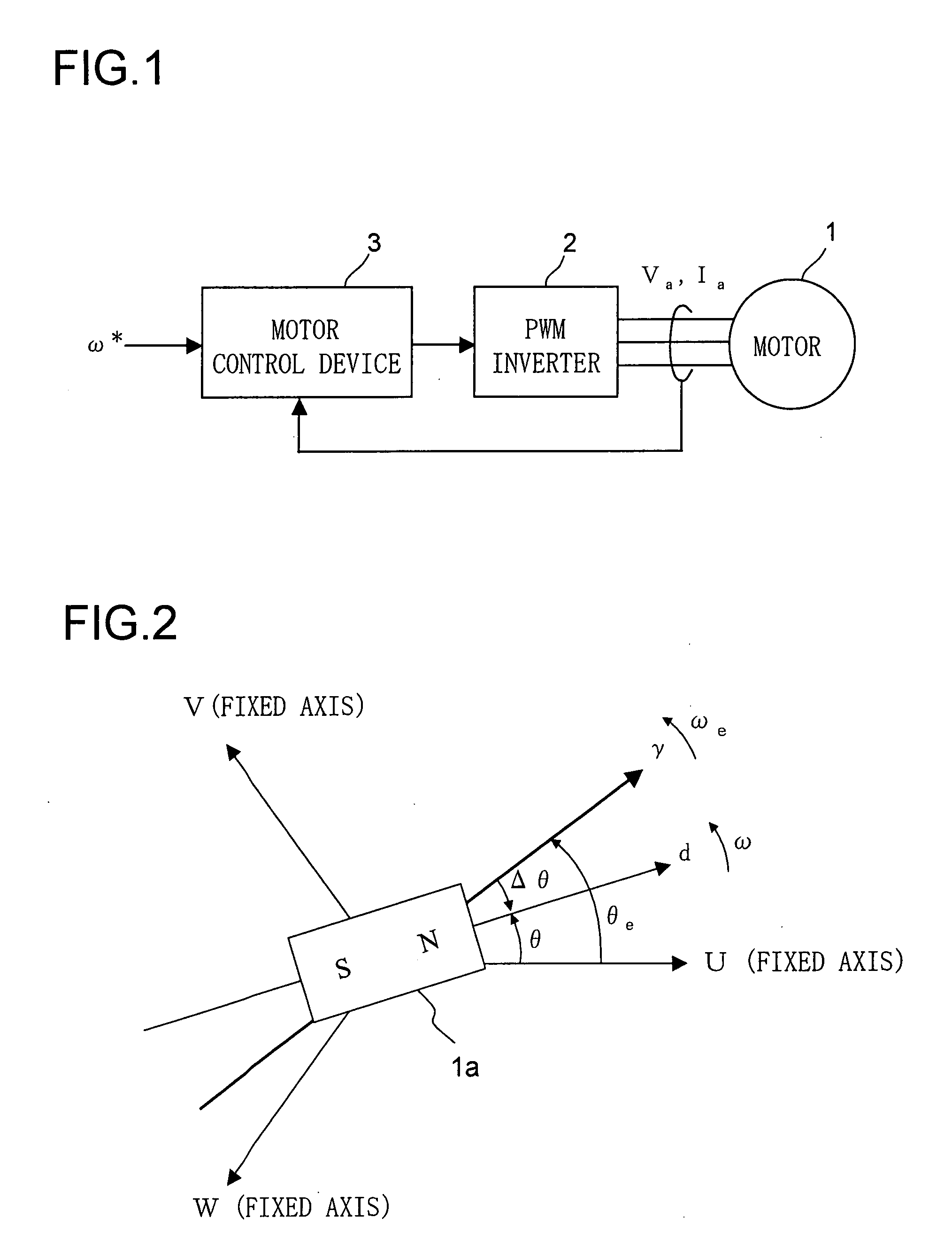
[0074]FIG. 1 is a block configuration diagram of a motor drive system according to a first embodiment of the invention. The reference numeral 1 represents a three-phase permanent-magnet synchronous motor 1 (hereinafter referred to simply as “the motor 1”) that has a permanent magnet on a rotor (unillustrated) and that has an armature winding on a stator (unillustrated). The motor 1 is a salient-pole motor (a motor having a salient pole) as exemplified by an interior permanent magnet synchronous motor.
[0075]The reference numeral 2 represents a PWM (pulse-width modulation) inverter that supplies the motor 1 with three-phase alternating-current voltages of U-, V-, and W-phases according to the position of the rotor of the motor 1. The voltage supplied to the motor 1 is referred to as the motor voltage (armature voltage) Va, and the current supplied from the PWM inverter 2 to the motor 1 is referred to as the motor current (armature current) Ia.
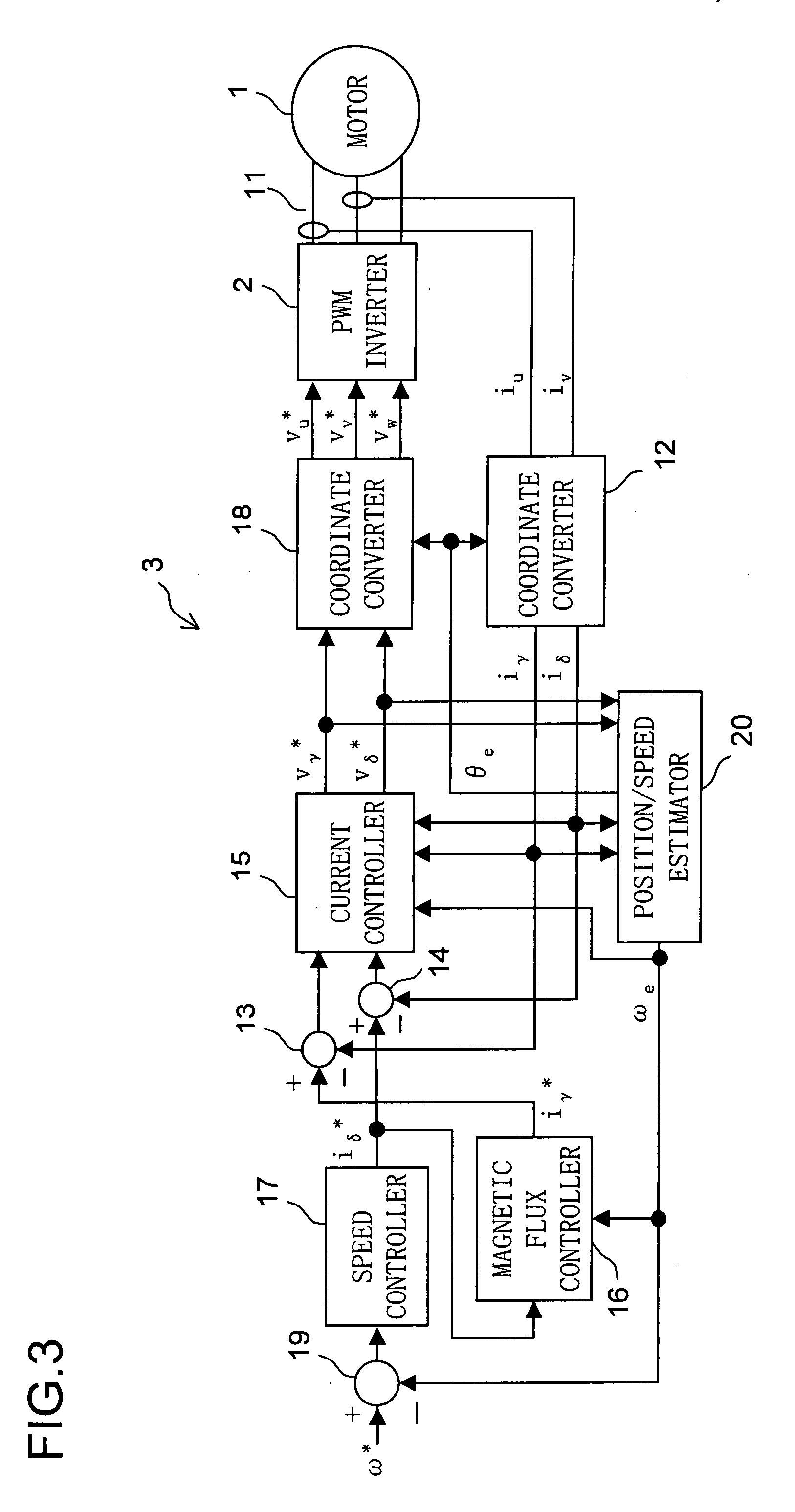
[0076]The reference numeral 3 represents a...
second embodiment
[0130]Next, a second embodiment of the invention will be described as one involving switching among different control methods—the feature with which one of the main objects of the invention is achieved. Throughout all the embodiments, that is, the first embodiment described above, this embodiment, and the following embodiments described later, unless otherwise described, the same parts are identified by the same reference numerals, and the same values, directions, etc. are identified by the same symbols (such as θ and ω). Accordingly, in principle, no overlapping explanations will be repeated for the parts, values, directions, etc. that bear the same reference numerals and symbols once they have been described.
[0131]FIG. 10 is a block configuration diagram of a motor drive system according to a second embodiment of the invention. The motor drive system according to the second embodiment includes a motor 1, an inverter 2, and a motor control device 3a.
[0132]The motor control device ...
third embodiment
[0195]The switching processor 203 shown in FIG. 15 may be made to function simply as a switch that switches between the first and second input values. Now, an example where the switching processor 203 is made to function as a switch will be described as a third embodiment of the invention. All the description of the second embodiment applies also to this embodiment unless inconsistent.
[0196]FIG. 19 is an internal block diagram of the position / speed estimator 40b (hereinafter referred to simply as “the estimator 40b”) according to the third embodiment. In the estimator 40b, the switching processor functions as a switch. The switching processor in the estimator 40b is called the switching processor 203a. The switching processor 203a provides an example of the configuration of the switching processor 203. The estimator 40b can be used as the estimator 40 shown in FIG. 14.
[0197]The estimator 40b shown in FIG. 19 differs from the estimator 40a shown in FIG. 15 in that the switching proce...
PUM
 Abstract
Description
Claims
Application Information
 - R&D
- Intellectual Property
- Life Sciences
- Materials
- Tech Scout
- Unparalleled Data Quality
- Higher Quality Content
- 60% Fewer Hallucinations
Browse by: Latest US Patents, China's latest patents, Technical Efficacy Thesaurus, Application Domain, Technology Topic, Popular Technical Reports.
© 2025 PatSnap. All rights reserved.Legal|Privacy policy|Modern Slavery Act Transparency Statement|Sitemap|About US| Contact US: help@patsnap.com


