Liquid crystal display device

Inactive Publication Date: 2008-01-03
HITACHI DISPLAYS
View PDF3 Cites 38 Cited by
  • Summary
  • Abstract
  • Description
  • Claims
  • Application Information

AI Technical Summary

Benefits of technology

[0015]Hereinafter, mention will be made of means for attaining, in the present invention, an optical distribution having anisotropy by means of the overall structure of the package. Based on the transverse direction and the longitudinal direction, or the horizontal direction and the vertical direction, it is possible to take the backlight light source to be an illuminating device having anisotropy, by providing an asymmetric structure. E.g., in the horizontal and transverse direction, the radiation angle distribution is extended to radiation angles greater than the direction vertical to the board and the distribution is made to have peak strength, and in the vertical and longitudinal direction, the radiation angle distribution is narrowed, so, depending on the use, it becomes valid to make the distribution into a diffuse one in which the radiation angles are restricted. As a result of this, in liquid crystal display devices, e.g. in large-sized liquid crystal television sets

Problems solved by technology

In the aforementioned JP-A-2003-8068, JP-A-2003-8081, and JP-A-2004-319458, attempts are made at controlling the radiation angle distribution of an element, but the cancellation of bright spots and chromaticity distribution is not sufficient, so it is not necessarily possible to provide a homogeneous and stable brightness distr

Method used


Image

  • Liquid crystal display device
  • Liquid crystal display device
  • Liquid crystal display device

Examples


first embodiment

[0049]Using FIG. 1 to FIG. 14, Embodiment 1 of the present invention will be explained.

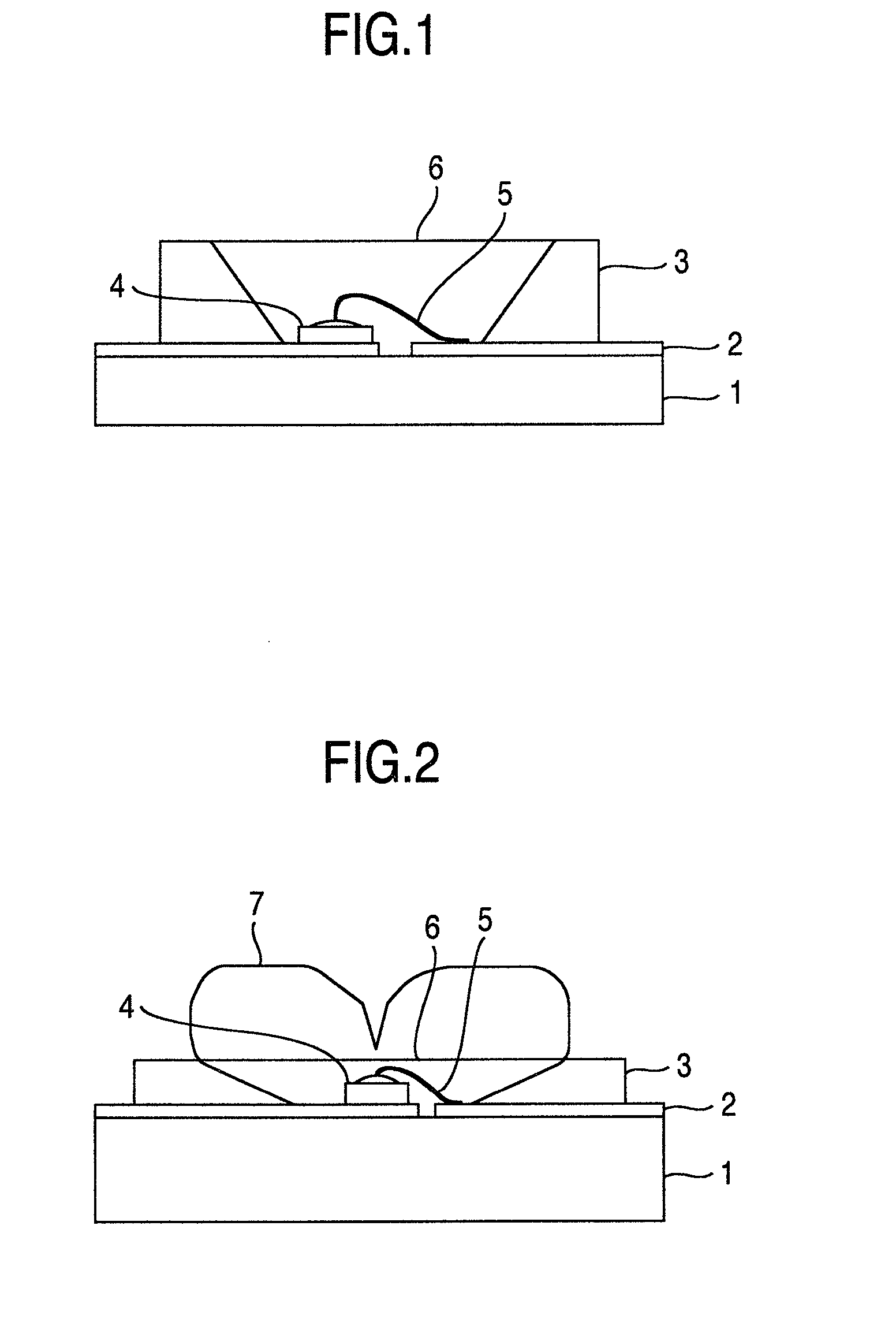
[0050]In the conventional example, as shown in FIG. 1, it is known, as light-emitting diode (LED) elements used as light sources of illumination devices or light source backlight modules, for the same to be integrated as a surface-mounted package structure. E.g., as shown in FIG. 1, an interconnection 2 is formed and a reflector plate 3 is structured in an integrated fashion on a metal board with an insulating layer included, a ceramic board, or a glass epoxy board 1. Next, there is taken an LED element 4 mounted by wire bonding based on a wire 5 shown in FIG. 1. Further, an LED light source with a surface-mounted package structure is prepared by means of sealing the LED element using a transparent resin part 6.

[0051]In the present embodiment, assuming a surface mounted package structure, in the same way as in the prior art example, after preparing up to transparent resin part 6, the LED element l...

second embodiment

[0060]Using FIG. 15 to FIG. 17, Embodiment 2 of the present invention will be explained.

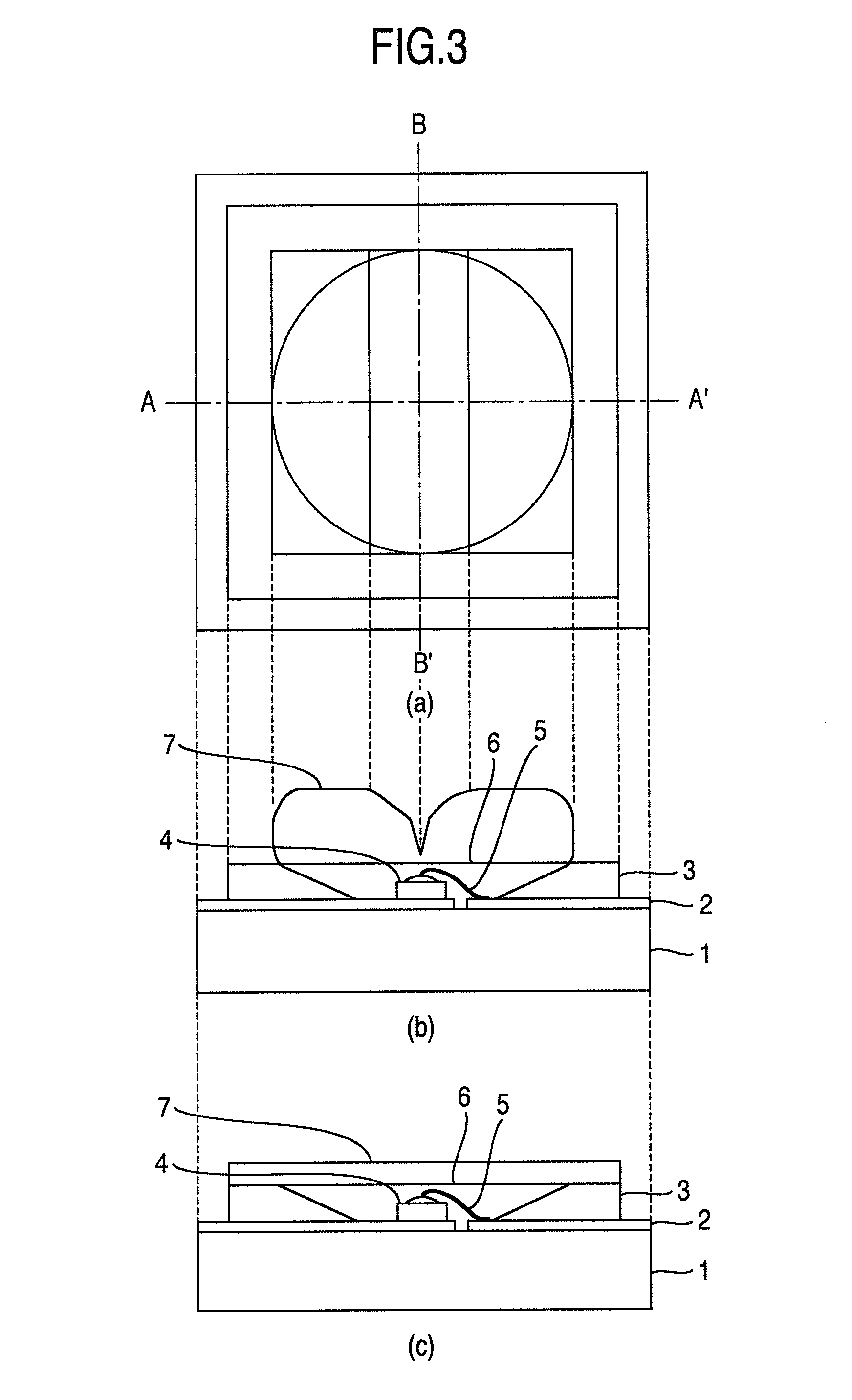
[0061]In the present embodiment, exactly in the same way as for Embodiment 1, an LED light source with a package structure is produced, but, as shown in FIGS. 15A, 15B, and 15C, after producing a package structure, reflector plate 3 shown in the cross section of FIG. 15C is set to be higher than LED element 4, and is set so as to be on the same order as, or greater than, the height of transparent resin part 7 formed with transparent resin. In this way, with respect to a specific direction, the height of the reflector plate is made to correspond and the emitted light distribution of the LED element is controlled, the shape of the radiation angle distribution is controlled. As for the radiation angle distribution of the LED element obtained with the present embodiment, it is clear that, by calculation, it can be obtained having anisotropy, as shown in FIGS. 16A and 16B. I.e., in the direction of li...

third embodiment

[0065]Using FIG. 18 to FIG. 24, Embodiment 3 of the present invention will be explained.

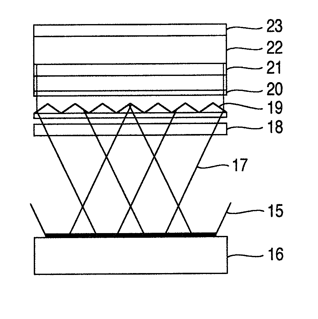
[0066]In the present embodiment, indications are given regarding the structure of a packaged light source and a liquid crystal backlight light source module. In the package structure of the present embodiment, there are cases where there are chosen four independently configured packages handling each of four elements, a red LED element 11, a green LED element 12, a green LED element 13, and a blue LED element 14, as shown in FIG. 18, and each packaged light source 15 is arranged in a backlight module housing 16 as shown in FIG. 19; and there are cases where red LED element 11, green LED element 12, green LED element 13, and blue LED element 14 are integrated into the same package, as shown in FIG. 20, and each package 15 is arranged in a backlight module housing 16, as shown in FIG. 21. It is possible to make the structure and arrangement of the packages correspond to a target specification. In e...


PUM


Abstract

There is explored the structure of an illumination device having a board, an interconnection and a reflector plate arranged on the aforementioned board, an LED element connected to the aforementioned interconnection, and a transparent resin part sealing the aforementioned LED element; wherein the aforementioned transparent resin part has a recess in the top face and the aforementioned recess has a shape taking as the major axis some axial direction in the plane of the aforementioned board. Further, the structure of a liquid crystal display device using this illumination device is explored. With the illumination device or a liquid crystal backlight light source module, it is possible to implement a light source for implementing an area control function and having the required homogeneous brightness and chromaticity distribution.

Description

BACKGROUND OF THE INVENTION[0001]1. Field of the Invention[0002]The present invention pertains to the structure of an illumination device using LED (light emitting diode) elements and pertains in particular to the structure of liquid crystal display devices acting as the backlight of this illumination device.[0003]The contents of the present invention can be applied as a the light source of an illumination device or as a backlight light source module applicable to a large-sized liquid crystal television set or a mid- or small-sized liquid crystal display device such as for a cellular phone or a Personal Computer.[0004]2. Description of the Related Art[0005]As the backlight light source of liquid crystal television sets representative of liquid crystal display devices, modules equipped with LED elements have in recent years come to be developed. Unlike small-sized liquid crystal display devices for mobile telephones and the like which are equipped with white LEDs using fluorescent ma...

Claims


Application Information

Patent Timeline
IPC IPC(8): F21V7/00H01L33/62
CPCG02F1/133603H01L2924/1815H01L33/58H01L33/54H01L2224/48465H01L2224/48091H01L2924/3025H01L2224/45144H01L2924/00014H01L2924/00
Inventor TANAKA, TOSHIAKIKANEKO, HIROKIHIYAMA, IKUO
Owner HITACHI DISPLAYS
Why Eureka
Try Eureka