X-ray ct apparatus and x-ray ct imaging method
- Summary
- Abstract
- Description
- Claims
- Application Information
AI Technical Summary
Benefits of technology
Problems solved by technology
Method used
Image

Examples
embodiment 1
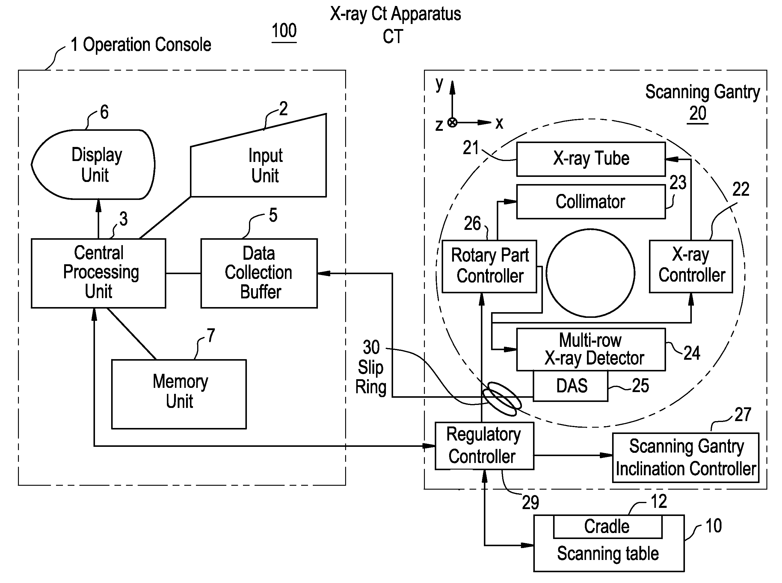
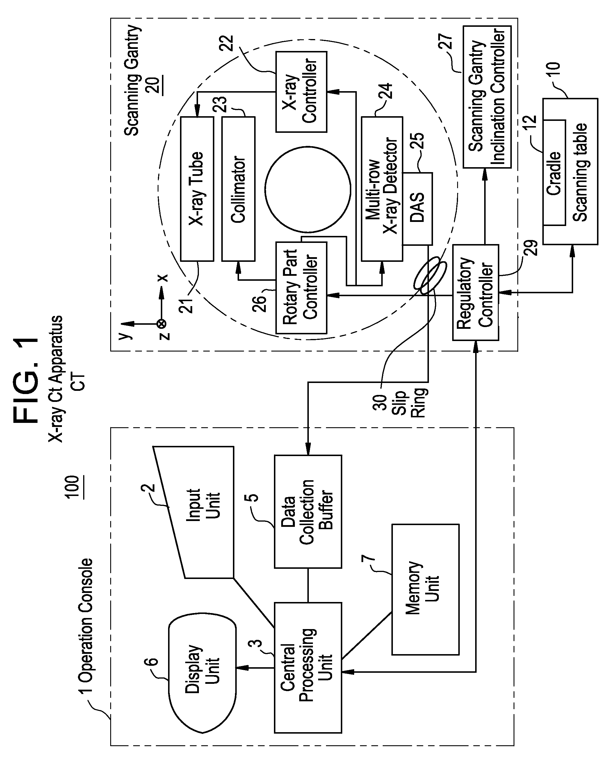
[0087]FIG. 1 is a configurational block diagram showing an X-ray CT apparatus pertaining to Embodiment 1.
[0088]This X-ray CT apparatus 100 is equipped with an operation console 1, an scanning table 10 and a scanning gantry 20.
[0089]The operation console 1 is provided with an input unit 2 which accepts inputs by the operator, a central processing unit 3 which executes pre-treatments, image reconstruction processing, post-treatments and so forth, a data acquisition buffer 5 which acquires projection data acquired by the scanning gantry 20, a display unit 6 which displays tomograms reconstructed from projection data obtained by pre-treating acquired projection data, and a memory unit 7 which stores programs, data, projection data and X-ray tomograms.
[0090]The scanning table 10 is provided with a cradle 12 which brings a subject mounted thereover in and out through an opening in the scanning gantry 20. The cradle 12 is moved up and down and linearly by a motor built into the scanning ta...
embodiment 2
[0157]It is also possible to keep the width of the X-ray beam at D as in the conventional practice and use the same conditions as in Embodiment 1 in other respects as shown in FIG. 21.
[0158]In Embodiment 2 as well, unevenness in picture quality dependent on the position of the reconstruction plane can be improved. Incidentally, an increase in irradiation can be avoided by restraining the X-ray dose and the X-ray tube current.
[0159]It is also possible to keep the interval between one scanning position and another at D as in the conventional practice and prevent the X-ray beam from widening both forward and backward in the linear transfer direction beyond the range in which projection data D0 are to be acquired as shown in FIG. 22.
[0160]Embodiment 3 can also help improve the picture quality of the tomogram at both ends. The range of irradiation can be reduced, too.
embodiment 4
[0161]It is also possible to keep the width of the X-ray beam at D as in the conventional practice and keep the interval between one scanning position and another at not more than D (exactly or approximately D / 2 in FIG. 22) as shown in FIG. 23.
[0162]Embodiment 4 can also help improve the picture quality of the tomogram positioned between one scanning position and another. Incidentally, by restraining the X-ray dose and the X-ray tube current, an increase in irradiation due to keeping the interval between one scanning position and another at D can be avoided.
PUM
 Abstract
Description
Claims
Application Information
 - Generate Ideas
- Intellectual Property
- Life Sciences
- Materials
- Tech Scout
- Unparalleled Data Quality
- Higher Quality Content
- 60% Fewer Hallucinations
Browse by: Latest US Patents, China's latest patents, Technical Efficacy Thesaurus, Application Domain, Technology Topic, Popular Technical Reports.
© 2025 PatSnap. All rights reserved.Legal|Privacy policy|Modern Slavery Act Transparency Statement|Sitemap|About US| Contact US: help@patsnap.com