
Providing stress uniformity in a semiconductor device

a technology of stress uniformity and semiconductor devices, which is applied in the direction of semiconductor devices, basic electric elements, electrical appliances, etc., can solve the problems of reducing the concentration of dopant a less attractive approach, affecting the threshold voltage of the transistor device, and requiring a considerable modification of the stress-creating layer

Active Publication Date: 2008-01-03
CONVERSANT INTPROP MANAGEMENT INC
View PDF17 Cites 31 Cited by
  • Summary
  • Abstract
  • Description
  • Claims
  • Application Information

AI Technical Summary

Benefits of technology

"The present invention provides a method and device for forming functional features on a semiconductor layer in a first region and a non-functional feature adjacent to the functional features on a periphery of the region. A stress-inducing layer is formed over at least a portion of the functional features and the non-functional feature. The technical effect of this invention is to improve the performance and reliability of semiconductor devices by inducing stress on the semiconductor layer and improving the stability of the device."

Problems solved by technology

Reducing the dopant concentration in the channel region, however, significantly affects the threshold voltage of the transistor device.
This makes the reduction of dopant concentration a less attractive approach.
A problem with the method of forming field effect transistors having stressed channel regions according to the state of the art is that the formation of the stress-creating layer requires a considerable modification of conventional and well-approved techniques used for the formation of field effect transistors.
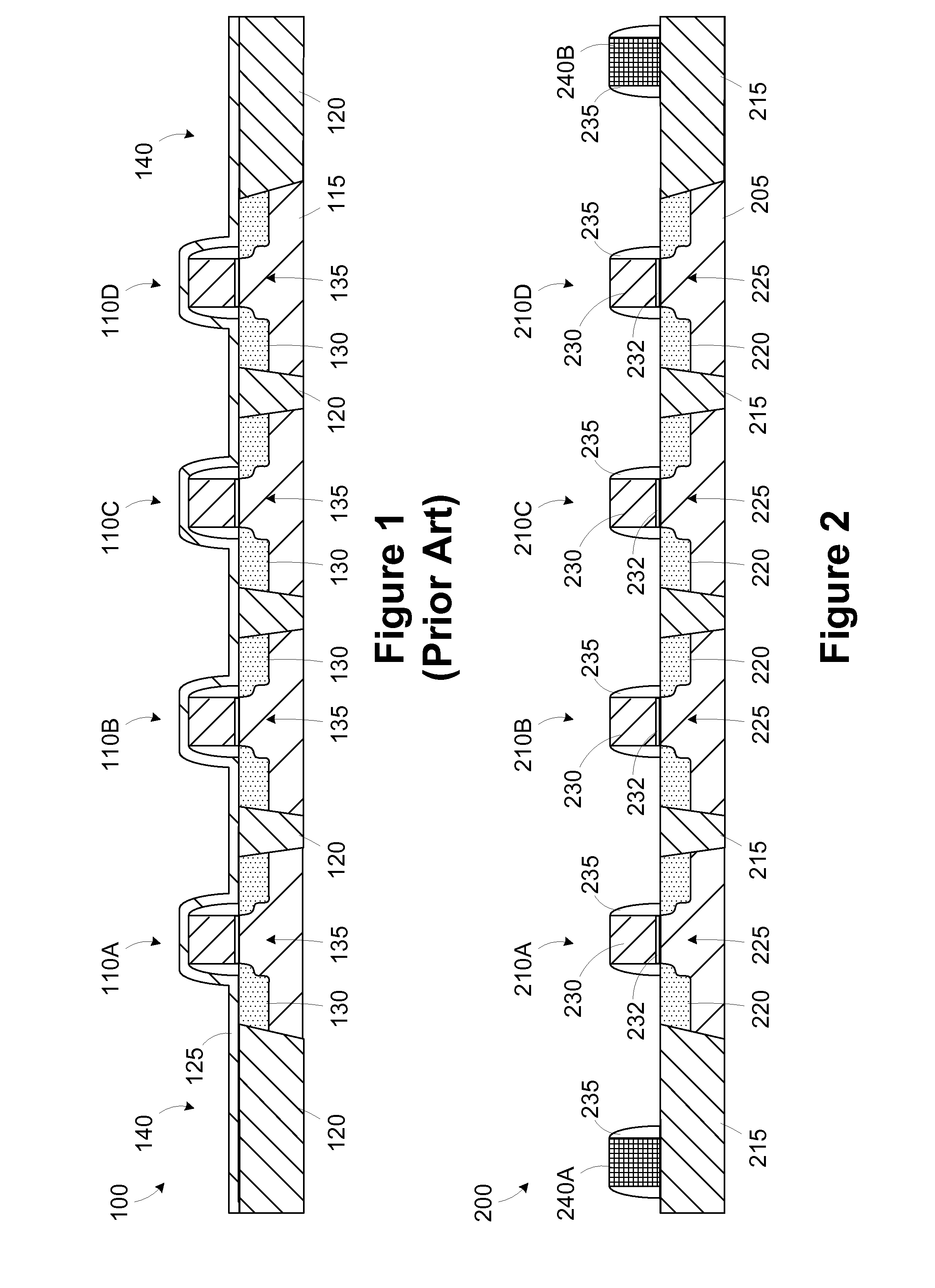
Another issue is that the physical layout of the semiconductor device affects the stress uniformity locally and across the wafer.
Because the layout includes regions with differing pattern densities, the induced stresses are not uniform across an individual die.
Stress variation across the collection of transistors can result in performance variation, which can, in turn, reduce the grade and profitability of the device 100.

Method used


Image

  • Providing stress uniformity in a semiconductor device
  • Providing stress uniformity in a semiconductor device
  • Providing stress uniformity in a semiconductor device

Examples


Embodiment Construction

[0023]One or more specific embodiments of the present invention will be described below. It is specifically intended that the present invention not be limited to the embodiments and illustrations contained herein, but include modified forms of those embodiments including portions of the embodiments and combinations of elements of different embodiments as come within the scope of the following claims. It should be appreciated that in the development of any such actual implementation, as in any engineering or design project, numerous implementation-specific decisions must be made to achieve the developers' specific goals, such as compliance with system-related and business related constraints, which may vary from one implementation to another. Moreover, it should be appreciated that such a development effort might be complex and time consuming, but would nevertheless be a routine undertaking of design, fabrication, and manufacture for those of ordinary skill having the benefit of this...


PUM


Abstract

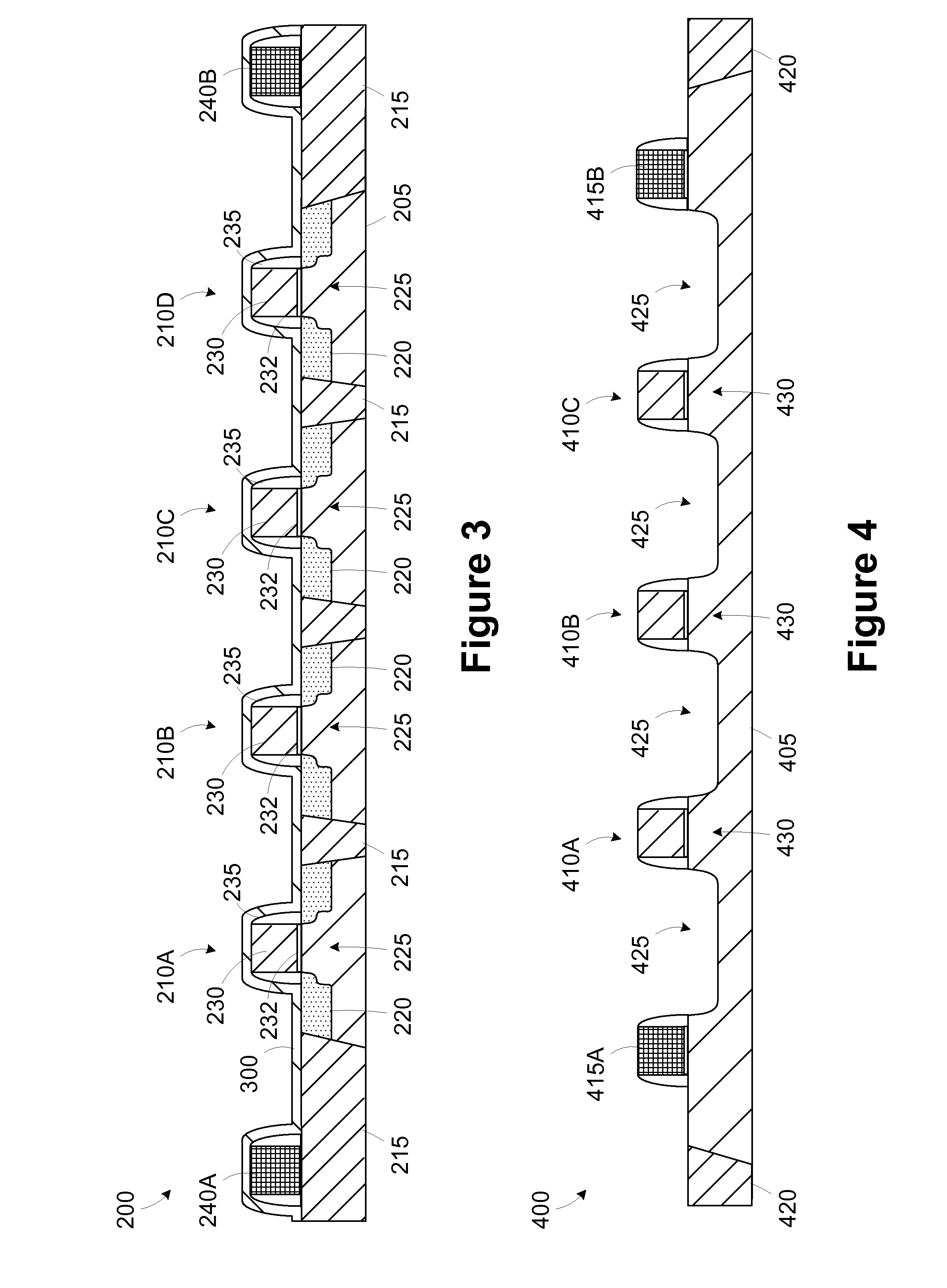
A method includes forming a plurality of functional features on a semiconductor layer in a first region. A non-functional feature corresponding to the functional feature is formed adjacent at least one of the functional features disposed on a periphery of the region. A stress-inducing layer is formed over at least a portion of the functional features and the non-functional feature. A device includes a semiconductor layer, a first dummy gate electrode, and a stress-inducing layer. The plurality of transistor gate electrodes is formed above the semiconductor layer. The plurality includes at least a first end gate electrode, a second end gate electrode, and at least one interior gate electrode. The first dummy gate electrode is disposed proximate the first end gate electrode. The stress-inducing layer is disposed over at least a portion of the plurality of transistor gate electrodes and the first dummy gate electrode.

Description

CROSS-REFERENCE TO RELATED APPLICATIONS[0001]Not applicable.STATEMENT REGARDING FEDERALLY SPONSORED RESEARCH OR DEVELOPMENT[0002]Not ApplicableBACKGROUND OF THE INVENTION[0003]The present invention relates generally to semiconductor manufacturing and, more particularly, to the use of a feature to provide stress uniformity.[0004]Integrated circuits comprise a large number of individual circuit elements, such as transistors, capacitors and resistors and the like. These elements are connected internally to form complex circuits, such as memory devices, logic devices and microprocessors. The performance of integrated circuits can be improved by increasing the number of functional elements in the circuit to increase its functionality and / or by increasing the speed of operation of the circuit elements. A reduction of feature sizes allows the formation of a greater number of circuit elements on the same area, hence allowing an extension of the functionality of the circuit, and also reduces...

Claims


Application Information

Patent Timeline
Patent Type & Authority Applications(United States)
IPC IPC(8): H01L21/3205
CPCH01L21/823418H01L29/7848H01L29/7843H01L21/823814
Inventor CHEN, JIANMICHAEL, MARK W.
Owner CONVERSANT INTPROP MANAGEMENT INC
Learn More