Method of manufacturing a pattern

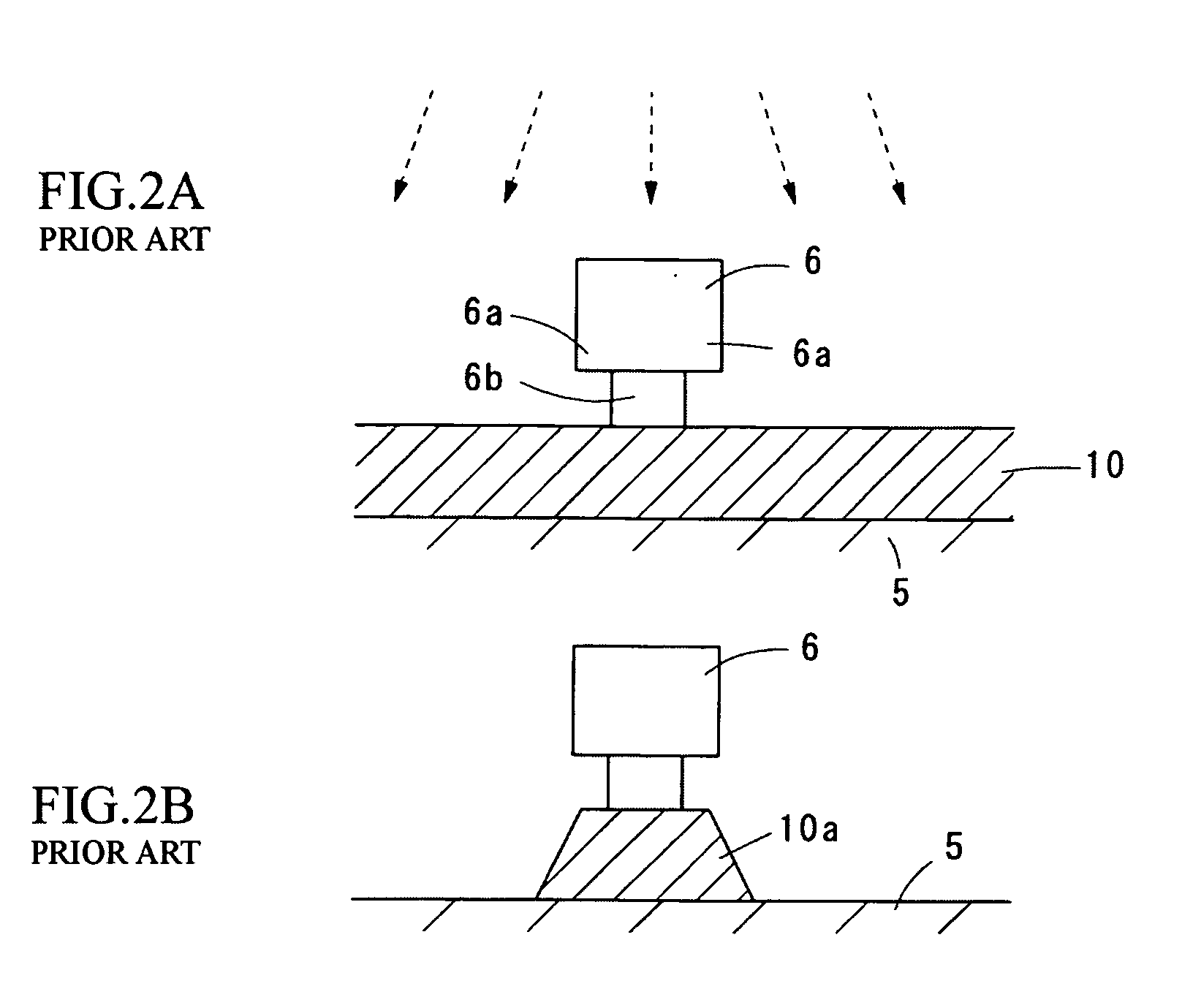
a manufacturing method and pattern technology, applied in the field of methods, can solve the problems of resist pattern b>6/b> collapsing, difficulty in precisely controlling the pattern, and method cease to be suitable, and achieve the effect of suppressing mask shape fluctuations, high precision, and high precision

Inactive Publication Date: 2008-01-03
FUJITSU LTD
View PDF6 Cites 6 Cited by
  • Summary
  • Abstract
  • Description
  • Claims
  • Application Information

AI Technical Summary

Benefits of technology

[0009]The present invention was conceived to solve the problem described above and it is an object of the present invention to provide a method of manufacturing a pattern that can form a mask with high precision when forming a precise pattern, such as when forming the read terminals of a magnetic head in a predetermined pattern, and can form a suitable pattern even when forming an extremely fine pattern such as read terminals.
[0011]Also, by forming the first mask layer of resin and forming the second mask layer of a resist material including silicon, it is possible to produce a clear difference in etching rates between the first mask layer and the second mask layer and to reliably form a mask with overhanging parts.
[0012]Also, by forming a protective layer, which is composed of a material that suppresses etching of the column part made of the first mask layer during the dry etching process, as an uppermost layer of the layer to be patterned, it is possible to suppress further etching of the column part during the dry etching process, thereby facilitating the operation during the dry etching process and making it possible to form a mask with no fluctuations in shape.
[0014]With the method of manufacturing a pattern according to the present invention, by providing a first mask layer and a second mask layer with different etching rates during the dry etching process and forming a mask by dry etching, compared to conventional wet etching, it is possible to form the mask with higher precision, to suppress fluctuations in the shape of the mask and form a pattern with high precision, and to improve the manufacturing yield of products.

Problems solved by technology

However, with a method that forms a resist pattern like that shown in FIGS. 2A and 2B by using a difference in etching rates when wet etching resist materials, it is difficult to precisely control the pattern.
As the recording density of recording media increases and read terminals 10a become increasingly narrow, this method ceases to be suitable.
For example, in a resist pattern 6 for patterning a read terminal, the main part of the pattern is only around 120 nm wide, and since the column part that supports such main part is extremely narrow, there is the problem of the formed resist pattern 6 collapsing if the column part is excessively etched by the wet etching.

Method used


Image

  • Method of manufacturing a pattern
  • Method of manufacturing a pattern
  • Method of manufacturing a pattern

Examples


Embodiment Construction

[0019]Preferred embodiments of the present invention will now be described in detail with reference to the attached drawings.

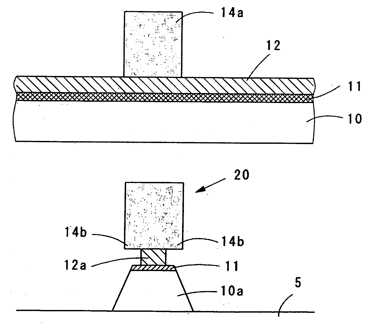
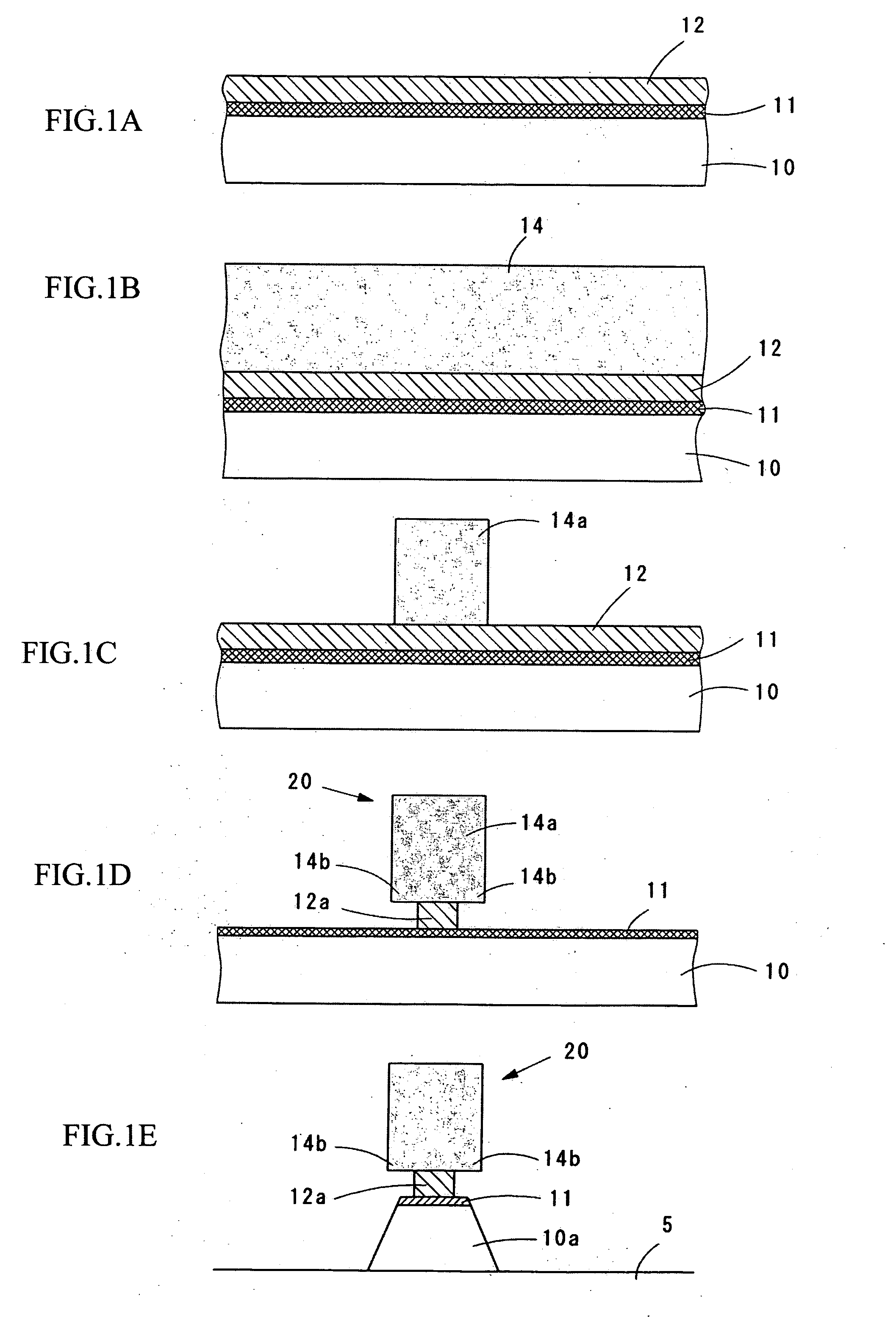
[0020]As an embodiment of a method of manufacturing a pattern according to the present invention, FIGS. 1A to 1E show a process that forms an element layer 10 as a layer to be patterned on the surface of a work and then forms a resist pattern as a mask for patterning the element layer 10 by ion milling during the manufacturing of a magnetoresistive effect element.

[0021]FIG. 1A shows a state where the element layer 10 has been formed and then an antireflection coating 12 made of resin has been formed as a first mask layer on the surface of the element layer 10. Note that the element layer 10 is formed by laminating a magnetic film, an insulating film, and the like for constructing read terminals. The multilayer construction of the element layer 10 will differ according to whether the element layer 10 is for a GMR element, a TMR element, or the like. Although th...


PUM


Abstract

A method of manufacturing a pattern can control the shape of a resist mask that forms read terminals in a predetermined pattern with high precision, so that the formation precision of the read terminals is improved and the manufacturing yield of the magnetic head is improved. The method includes: a step of forming a layer to be patterned on a substrate; a step of forming a first mask layer on the layer to be patterned; a step of forming a second mask layer, which has a lower etching rate during a dry etching process than the first mask layer, on the first mask layer; a step of exposing and developing the second-mask layer to form the second mask layer in a predetermined shape; and a step of removing exposed parts of the first mask layer that are exposed from the second mask layer by dry etching and dry etching a part of the first mask layer below the second mask layer from sides thereof to form a column part in the first mask layer that is narrower than the second mask, thereby forming a mask with overhanging parts.

Description

BACKGROUND OF THE INVENTION[0001]1. Field of the Invention[0002]The present invention relates to a method of manufacturing a pattern of a predetermined shape from a layer formed on a substrate, and in more detail to a method of manufacturing a pattern of a predetermined shape such as the shape of a magnetoresistive effect element used in the read head of a magnetic head.[0003]2. Related Art[0004]As shown in FIG. 2A, during a process that forms a magnetoresistive effect element, after an element layer 10 that will become a read element has been formed on the surface of a work 5, a resist pattern 6 which has overhanging parts 6a formed in the side surfaces thereof is formed on the surface of the element layer 10. The resist pattern 6 is used as a mask when patterning the element layer 10 into predetermined patterns (widths) by ion milling to form a read terminal 10a. [0005]The overhanging parts 6a are provided in the side surfaces of the resist pattern 6 to restrict the area irradiate...

Claims


Application Information

Patent Timeline
Patent Type & Authority Applications(United States)
IPC IPC(8): H01L21/44
CPCG11B5/3906G11B5/3163G03F7/00
Inventor KOJIMA, TAKASHI
Owner FUJITSU LTD
Why Eureka
Try Eureka