Dry mate connector

a technology of connectors and mates, applied in the direction of coupling device connections, instruments, optical elements, etc., can solve the problems of connector failure, connector deformation, and connectors that are not suitable for high reliability applications, and achieve high manufacturing costs, improve reliability, and enhance the state of the art

Active Publication Date: 2008-01-03
TELEDYNE INSTR INC
View PDF13 Cites 33 Cited by
  • Summary
  • Abstract
  • Description
  • Claims
  • Application Information

AI Technical Summary

Benefits of technology

[0014]The design enhances the state of the art by improving reliability and by addressing issues with currently available dry ma

Problems solved by technology

Interference fit connectors are typically not suitable for high reliability applications.
Their somewhat deformable bodies do not allow the precise contact alignment required for optical circuits.
If even a single droplet of water or a bit of dampness enters the contact area prior to complete engagement, the connector fails electrically.
These connectors have no internal protection that prevents contact-to-contact or contact-to-shell electrical shorting in such circumstances.
These rigid body dry-mate connectors, however, are not manufactured with sur

Method used


Image

  • Dry mate connector
  • Dry mate connector
  • Dry mate connector

Examples


Embodiment Construction

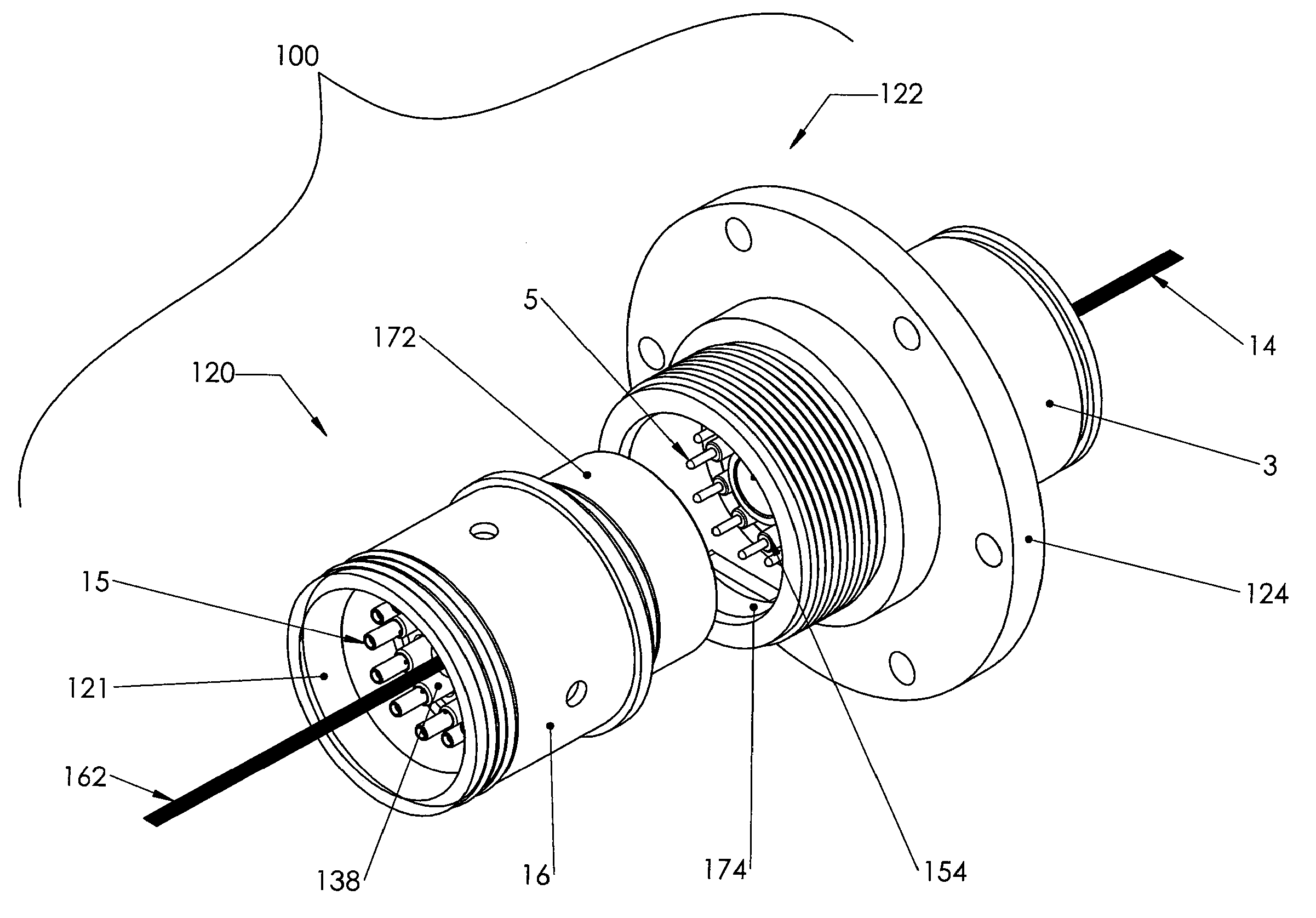
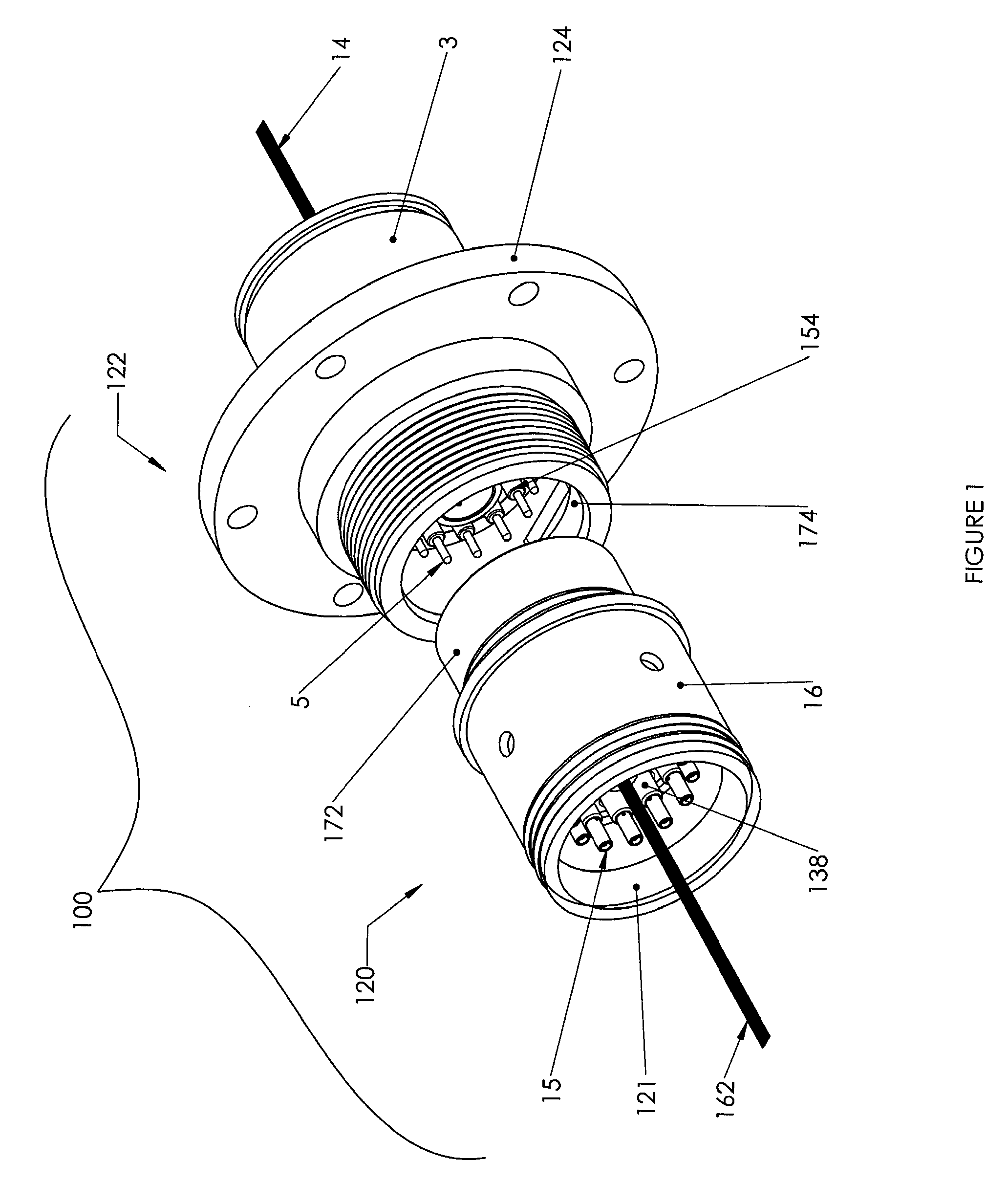
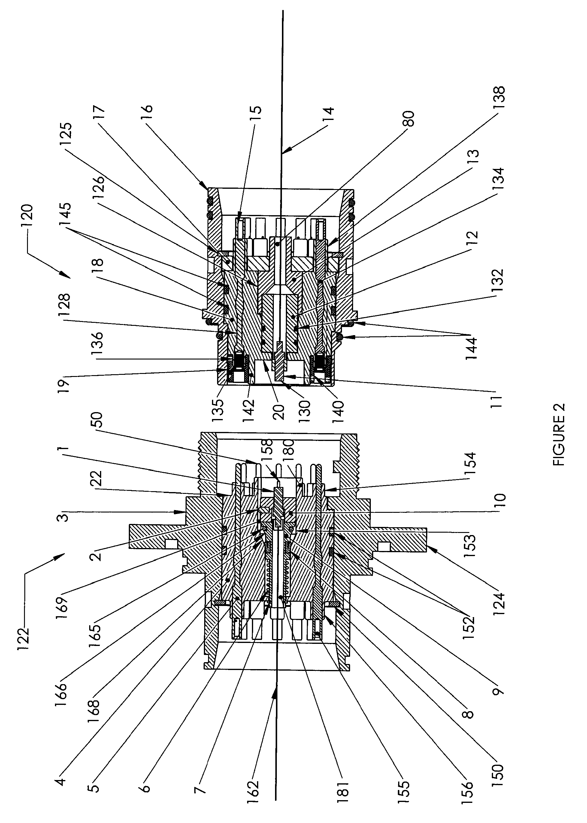
[0026]Certain embodiments as disclosed herein provide for a dry-mate connector for simultaneously joining multiple electrical and / or optical circuits in a dry environment before immersing the connector in a harsh environment such as deep ocean depths.

[0027]After reading this description it will become apparent to one skilled in the art how to implement the invention in various alternative embodiments and alternative applications. However, although various embodiments of the present invention are described herein, it is understood that these embodiments are presented by way of example only, and not limitation. As such, this detailed description of various alternative embodiments should not be construed to limit the scope or breadth of the present invention as set forth in the appended claims.

[0028]FIGS. 1 to 4 illustrate a dry-mate hybrid or electro-optical connector 100 according to one embodiment, while FIGS. 5, 7, and 8 illustrate one part of the connector in more detail and FIGS....


PUM


Abstract

A dry-mate connector has nipples on the front or mating side of the electrical conductors on both the plug and receptacle units which cooperate with an elastomeric seal on the mating end of one of the units to provide an individual seal around each electrical circuit in the mated condition. In a hybrid version of the connector, an optical contact assembly is provided in each unit which has a multi-fiber ferrule at the mating end of the assembly, allowing a high contact density to be achieved in a relatively small space.

Description

RELATED APPLICATION [0001]The present application claims the benefit of co-pending U.S. provisional patent application No. 60 / 817,826 filed Jun. 30, 2006, which is incorporated herein by reference in its entirety.BACKGROUND [0002]1. Field of the Invention[0003]The present invention relates generally to dry-mate connectors which are intended to be mated in a dry environment and then exposed to a harsh working environment, such as seawater.[0004]2. Related Art[0005]Dry-mate connectors typically consist of plug and receptacle units which, when mated together, form a sealed chamber around the contact elements. The plug unit typically contains a plurality of contact probes or pins to which fiber-optic or electrical leads are terminated. The receptacle unit contains a corresponding number of sockets into whose terminal ends a corresponding number of fiber-optic or electrical leads are terminated. The probes or pins are mated with the sockets when the two units are coupled together.[0006]O...

Claims


Application Information

Patent Timeline
IPC IPC(8): H01R13/73
CPCH01R13/5202H01R13/748H01R13/5219H01R13/523
Inventor CAIRNS, JAMES L.
Owner TELEDYNE INSTR INC
Why Eureka
Try Eureka