System and method for verifying calibration of a surgical device

a surgical device and calibration technology, applied in the field of surgical system and method, can solve the problems of reducing the surgeon's ability to view and access the anatomy, limited visibility, and limited access to the join

Active Publication Date: 2008-01-03
MAKO SURGICAL CORP
View PDF65 Cites 237 Cited by
  • Summary
  • Abstract
  • Description
  • Claims
  • Application Information

AI Technical Summary

Benefits of technology

[0069] As shown in FIG. 2A, the haptic device tracker 45 is disposed on the haptic device 30 and is adapted to enable the surgical system 10 to monitor a global or gross position of the haptic device 30 in physical space. In particular, the haptic device tracker 45 enables the surgical system 10 to determine whether the haptic device 30 has moved relative to other objects in the surgical environment, such as the patient. Such information is important because the tool 50 is attached to the haptic device 30. For example, if the user intentionally repositions or inadvertently bumps the haptic device 30 while cutting the femur F with the tool 50, the tracking system 40 will detect movement of the haptic device tracker 45. In response, the surgical system 10 can make appropriate adjustments to programs running on the computer 21 and / or the computer 31 to compensate for global or gross movement of the haptic device 30 (and the attached tool 50) relative to the femur F. As a result, integrity of the femur preparation process is maintained.

Problems solved by technology

One drawback of MIS is that the small incision size reduces a surgeon's ability to view and access the anatomy.
For example, in minimally invasive orthopedic joint replacement, limited visibility and limited access to the joint increase the complexity of assessing proper implant position and of reshaping bone.
As a result, accurate placement of implants may be more difficult.
Such techniques, however, typically require a large amount of specialized instrumentation, a lengthy training process, and a high degree of skill.
Moreover, operative results for a single surgeon and among various surgeons are not sufficiently predictable, repeatable, and / or accurate.
In orthopedic applications, one drawback of both MIS and traditional surgical approaches is that healthy as well as diseased bone is removed when the bone is prepared to receive the implant.
Another drawback of both MIS and traditional orthopedic surgical approaches is that such approaches do not enhance the surgeon's inherent surgical skill in a cooperative manner.
Although such systems enable precise bone resections for improved implant fit and placement, they act autonomously (rather than cooperatively with the surgeon) and thus require the surgeon to cede a degree of control to the robot.
Additional drawbacks of autonomous systems include the large size of the robot, poor ergonomics, the need to rigidly clamp the bone during registration and cutting, increased incision length for adequate robot access, and limited acceptance by surgeons and regulatory agencies due to the autonomous nature of the system.
One drawback of conventional interactive robotic systems is that such systems lack the ability to adapt surgical planning and navigation in real-time to a dynamic intraoperative environment.
The interactive robotic system also requires the relevant anatomy to be rigidly restrained and the robotic system to be fixed in a gross position and thus lacks real-time adaptability to the intraoperative scene.
Moreover, the 3-DOF configuration of the arm and the requirement that the surgeon manipulate the arm using the force handle results in limited flexibility and dexterity, making the robotic system unsuitable for certain MIS applications.

Method used


Image

  • System and method for verifying calibration of a surgical device
  • System and method for verifying calibration of a surgical device
  • System and method for verifying calibration of a surgical device

Examples


Embodiment Construction

[0052] Presently preferred embodiments of the invention are illustrated in the drawings. Although this specification refers primarily to orthopedic procedures involving the knee joint, it should be understood that the subject matter described herein is applicable to other joints in the body, such as, for example, a shoulder, elbow, wrist, spine, hip, or ankle and to any other orthopedic and / or musculoskeletal implant, including implants of conventional materials and more exotic implants, such as orthobiologics, drug delivery implants, and cell delivery implants.

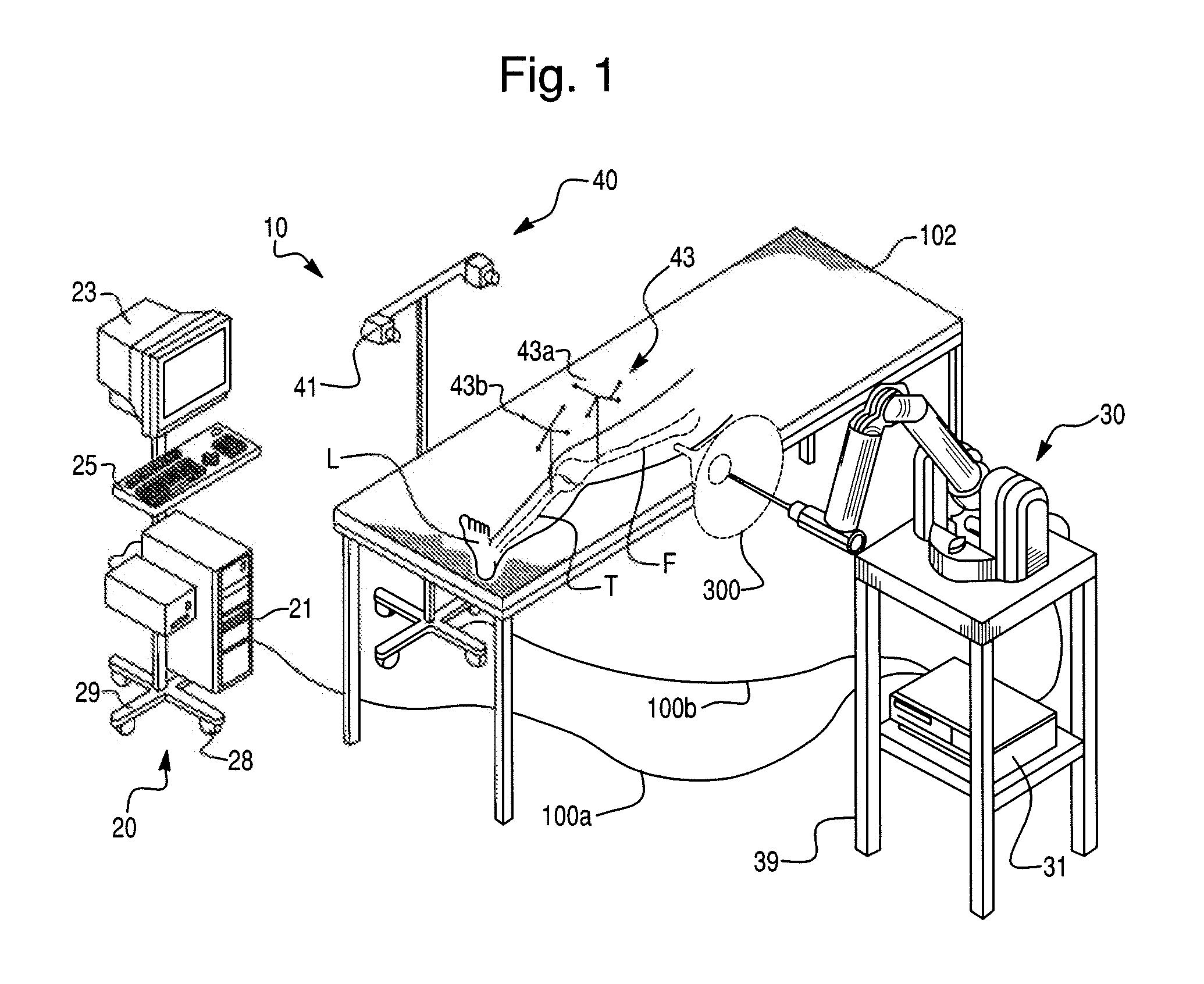
[0053]FIG. 1 shows an embodiment of a surgical system 10 according to the present invention. The surgical system 10 includes a computing system 20, a haptic device 30, and a tracking (or localizing) system 40. In operation, the surgical system 10 enables comprehensive, intraoperative surgical planning. The surgical system 10 also provides haptic guidance to a user (e.g., a surgeon) and / or limits the user's manipulation of th...


PUM


Abstract

The invention relates to a surgical system and, more particularly, to a surgical system and method for verifying calibration of a surgical device. The surgical system or method can be configured to perform the steps of: identifying an interface on an anatomy of a patient, determining a position of a checkpoint of the interface in a coordinate frame of reference, contacting the interface with a portion of a surgical tool of the surgical device, determining a position of the portion of the surgical tool in the coordinate frame of reference, and determining whether the position of the portion of the surgical tool has an expected correspondence to the position of the checkpoint. The interface may comprise a painted portion of a bone of the patient, a divot made in the bone, or a mechanical interface that includes a portion configured to be affixed to the bone and an interface portion that is configured to be contacted by the portion of the surgical tool.

Description

CROSS REFERENCE TO RELATED APPLICATIONS [0001] The present application claims priority to U.S. Provisional Patent Application Ser. No. 60 / 801,378, filed on May 19, 2006, which is hereby incorporated by reference in its entirety.BACKGROUND [0002] 1. Field of the Invention [0003] The invention relates to a surgical system and method and, more particularly, to a surgical system and method for verifying calibration of a surgical device. [0004] 2. Description of Related Art [0005] Minimally invasive surgery (MIS) is the performance of surgery through incisions that are considerably smaller than incisions used in traditional surgical approaches. For example, in an orthopedic application such as total knee replacement surgery, an MIS incision length may be in a range of about 4 to 6 inches whereas an incision length in traditional total knee surgery is typically in a range of about 6 to 12 inches. As a result of the smaller incision length, MIS procedures are generally less invasive than t...

Claims


Application Information

Patent Timeline
Patent Type & Authority Applications(United States)
IPC IPC(8): A61B19/00
CPCA61B17/1764A61B2019/5483A61B19/30A61B19/5244A61B19/56A61B2017/00119A61B2017/00694A61B2017/00712A61B2017/00725A61B2019/2234A61B2019/2242A61B2019/2292A61B2019/502A61B2019/507A61B2019/508A61B2019/5255A61B2019/5259A61B2019/5265A61B2019/5268A61B2019/527A61B2019/5287A61B2019/5289A61B19/2203A61B2090/3983A61B2034/102A61B2034/2055A61B2034/2068A61B2034/207A61B2090/363A61B34/71A61B34/25A61B2090/364A61B34/30A61B2034/305A61B34/76A61B90/03A61B2034/107A61B2034/108A61B2034/2059A61B2034/2065A61B34/20A61B34/10A61B2034/2072
Inventor ARATA, LOUISALY, SHERIFVAN VORHIS, ROBERTGLAUSER, SANDIBLACKWELL, TIMOTHYABOVITZ, RONYFERRE, MAURICE R.
Owner MAKO SURGICAL CORP
Why Eureka
Try Eureka