
Real time in-line hydrosonic water-in-fuel emulsion apparatus, process and system

Active Publication Date: 2008-01-10
COTTELL ERIC WILLIAM
View PDF17 Cites 13 Cited by
  • Summary
  • Abstract
  • Description
  • Claims
  • Application Information

AI Technical Summary

Benefits of technology

[0022] The invention of this system also includes the capability to automatically switch back and forth between the conventional fuel and emulsified fuel. The system may be installed without any modifications to the existing boiler or engine with little down time and even zero down time in the case of redundant conventional fuel systems. The system may be interfaced with existing boiler controls and combustion management computer system. The system results in numerous benefits such as reduced emissions, reduced fuel consumption, reduced maintenance and hence reduced life cycle cost. The reactor in the preferred embodiment comprises an anvil-encased spring. PRIOR ART
[0074] Other objectives of this invention reside in its simplicity, elegance of design, ease of manufacture, service and use and even aesthetics as will become apparent from the following brief description of the drawings and the detailed description of the concept embodiment.

Problems solved by technology

There is no continuous circulating loop and no means of integration of the delivery and return into an existing system nor any means of easy switch over between existing fuel and emulsified fuel.
However, this requires dedicated storage and return tanks and stability is not guaranteed.
Unfortunately none of the prior art devices singly or even in combination provide for all of the objectives as established by the inventor for this system as enumerated below.
Unfortunately none of the prior art devices singly or even in combination provides all of the features established by the inventor for this system as enumerated below.

Method used


Image

  • Real time in-line hydrosonic water-in-fuel emulsion apparatus, process and system
  • Real time in-line hydrosonic water-in-fuel emulsion apparatus, process and system
  • Real time in-line hydrosonic water-in-fuel emulsion apparatus, process and system

Examples


Embodiment Construction

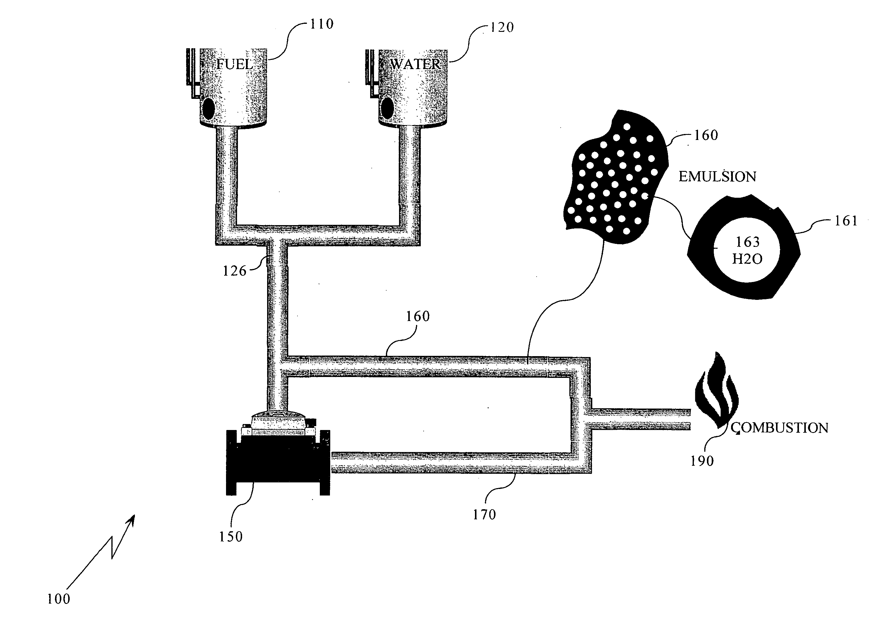
[0111] This invention is concerned with apparatus and method of benefaction of fuel by producing an intimate emulsion of water in oil at the point of combustion. As shown in the drawings wherein like numerals represent like parts throughout the several views, there is generally disclosed in FIG. 1 is a block diagram of the Real Time In-Line Hydrosonic Fuel-Water Emulsion Apparatus, Process and System of this invention complete with a Fuel Source 110, a water source 120, an emulsion unit near the point of combustion (AKA—Reactor) 150, oil 161& and water 162 in emulsion 160, a single water droplet 163, droplet of water 161 with film of oil 162 in emulsified fuel 160, an emulsified fuel circulating loop 170 having a high pressure side 171, a Valve or solenoid 172 and a low pressure side 173 and combustion unit 190.

[0112] The fuel viscosity may be changed by introducing a carbon atom, molecule or other equivalent particle at the center of the water droplet 163, so as to form a three la...


PUM

PropertyMeasurementUnit
Fractionaaaaaaaaaa
Fractionaaaaaaaaaa
Flow rateaaaaaaaaaa

Abstract

Devices, methods and system for combustion of an intimate emulsion of water-in-fuel without the use of chemical additives in order to reduce emissions and improve fuel economy with little or no engine or boiler de-rating or modifications. Apparatus and method for producing, combusting, storing and reducing viscosity of a fuel comprised of water and oil or other hydrocarbons, which is constituted as an emulsion without the need for chemical stabilizers by exposure to constant cavitation.

Description

RELATED DOCUMENT [0001] This application is based on provisional application Ser. No. 60 / 786,881 filed on Mar. 30, 2006. by the same inventor Eric Cottell then entitled, “Upstream Emission Control Process and Apparatus Comprising an Intimate Emulsion of Water-in-Fuel” and the applicant hereby claims priority there from.BACKGROUND [0002] This invention relates generally to the art and science of fossil fuels. More particularly it relates to hydrocarbon fuels. Even more particularly it relates to intimate emulsions of water in hydrocarbon fuels to increase their efficiency and reduce the environmental pollution. This invention is concerned with not only apparatus and method for producing more efficient economic fuel but also the combustion viscosity reduction and the production of energy from the fuel for a few specific applications such as engines boilers, automobiles, boats etc. THE PROBLEM [0003] The problem with prior art water-in-fuel emulsification systems is that they manufactu...

Claims


Application Information

Patent Timeline
IPC IPC(8): F17D1/14B01F25/60
CPCF17D1/17Y02T10/121F02M25/0225C10L1/328F02M25/0228B01F3/0807C10L2290/146C10L2250/084B01F5/0665B01F5/0681B01F5/10C10L2290/34Y10T137/85978Y10T137/0424B01F23/41B01F25/4413B01F25/4423B01F25/50Y02T10/12
Inventor COTTELL, ERIC WILLIAM
Owner COTTELL ERIC WILLIAM
Learn More