Heavy-duty circuit breaker with erosion-resistant short-circuit current routing

a circuit breaker and short-circuit current technology, applied in the direction of air-break switches, high-tension/heavy-dress switches, electrical equipment, etc., can solve the problems of increasing contact resistance, degrading the electrical contact between the contact tulip and the current-carrying element, and failure of the contact, so as to achieve the effect of convenient manufacture and installation

Inactive Publication Date: 2008-01-10
ABB TECH AG +1
View PDF7 Cites 7 Cited by
  • Summary
  • Abstract
  • Description
  • Claims
  • Application Information

AI Technical Summary

Benefits of technology

[0024] In one preferred embodiment, there is a second axial area in which a radial internal dimension of the erosion protection element is essentially the same as a radial internal dimension of the arcing contact piece. The radial internal dimension of the current-carrying element and the radial external dimension of the erosion protection element are particularly advantageously of the same magnitude (within manufacturing tolerances) in the axial area. In other words, a radial internal dimension of the erosion protection element is essentially of the same magnitude as the radial internal dimension of the arcing contact piece close to the flat contact. This allows the heavy-duty ...

Problems solved by technology

Unless adequate protection is provided, a hot-gas flow such as this can remove material from the current-carrying element and/or from the contact tulip, as a result of which this can lead to degradation of the electrical contact between the contact tulip and the current-carrying element.
This can result in increasing contact resistance, and even in failure of the contact.
The provision of a tube such as this composed of erosion-resistant material considerably reduces the c...

Method used


Image

  • Heavy-duty circuit breaker with erosion-resistant short-circuit current routing
  • Heavy-duty circuit breaker with erosion-resistant short-circuit current routing
  • Heavy-duty circuit breaker with erosion-resistant short-circuit current routing

Examples


Embodiment Construction

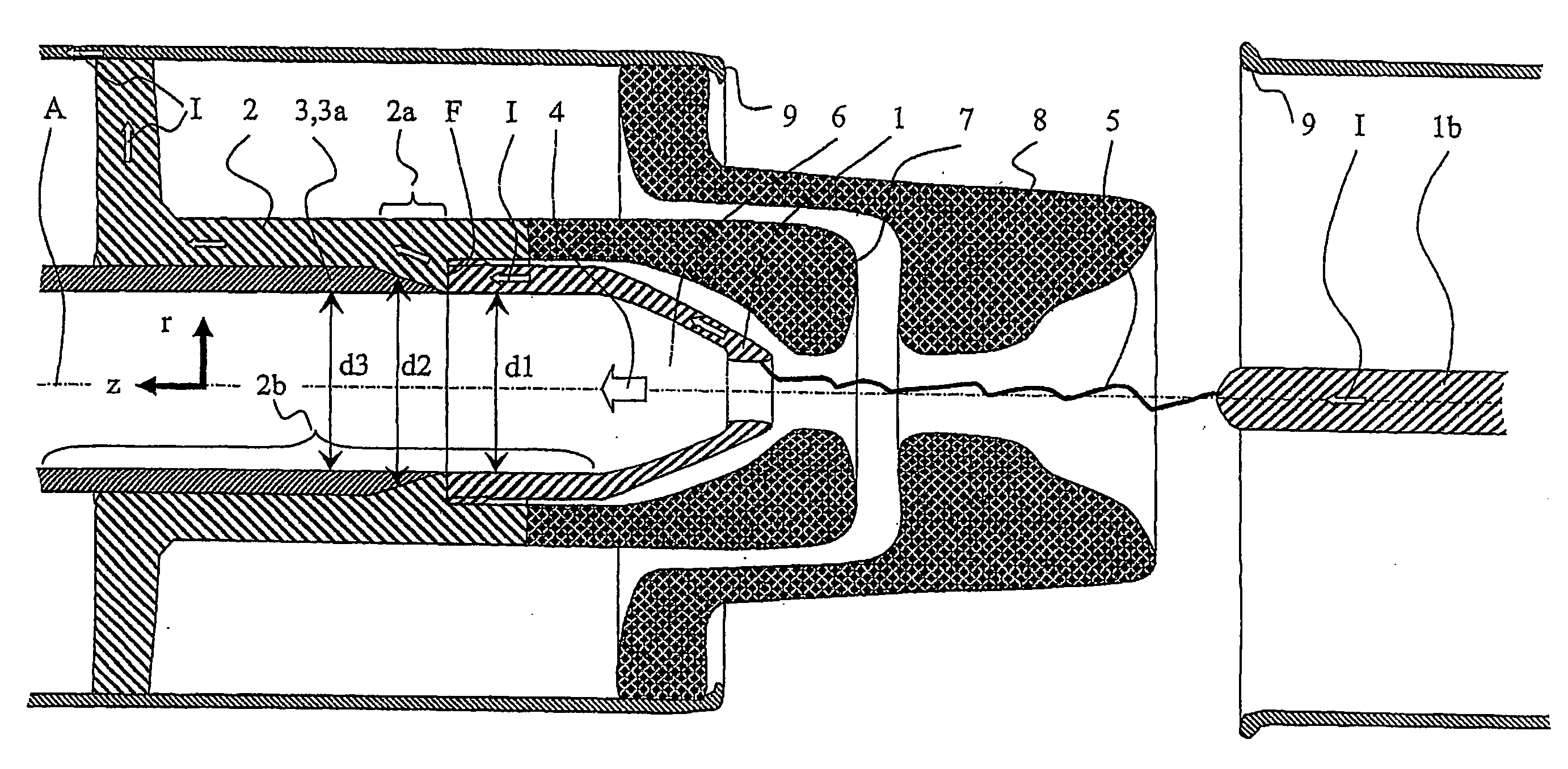
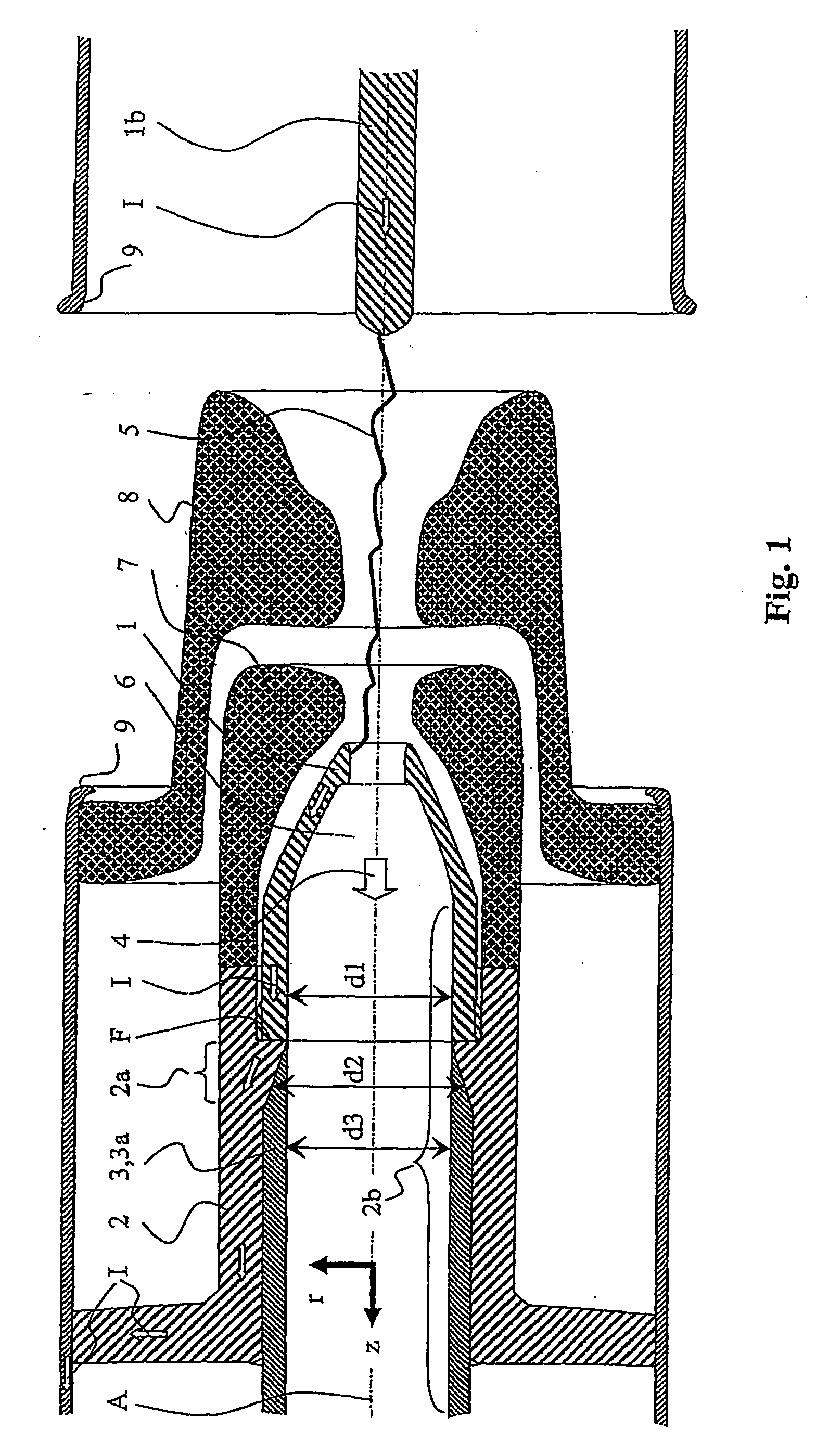
[0036]FIG. 1 shows, schematically and sectioned, a detail of a heavy-duty circuit-breaker according to the invention, in the open switching state. The heavy-duty circuit-breaker is essentially rotationally symmetrical with a rotation axis A, which defines an axial coordinate, annotated z, and a radial coordinate, annotated r. In order to open the switch, a rated-current contact system 9 which comprises two rated-current contacts 9 is opened first of all, so that the current flowing through the circuit breaker is commutated onto an arcing contact-piece system, which comprises two arcing contact pieces 1, 1b. After disconnection of the two arcing contact pieces 1, 1b, an arc 5 is struck between them, and a short-circuit current I, symbolized by thin open arrows, flows through the two arcing contact pieces 1, 1b.

[0037] The arcing contact piece 1 is in the form of a contact tulip with a multiplicity of contact fingers, and has an opening 6. A quenching gas 4 that is provided in the cir...


PUM


Abstract

The heavy-duty circuit-breaker having an axis (A) which defines an axial coordinate (z) parallel to the axis and a radial coordinate (r) at right angles to the axis, and having an arcing contact piece, a current-carrying element and an erosion protection element, with the arcing contact piece having an opening in order to carry an essentially axial flow of a gas which has been heated by an arc which may be based on the arcing contact piece, and together with the current-carrying element forms a flat contact (F) in order to carry a short-circuit current (I) which flows through the arcing contact piece and the current-carrying element for the time during which the arc burns, and with the erosion protection element essentially shielding the current-carrying element from the flow close to the flat contact (F), is characterized in that the current-carrying element has an axial area in which a radial internal dimension (d2) of the current-carrying element increases in steps or continuously as the distance from the flat contact (F), measured parallel to the axis (A), increases. The axial area is advantageously intended, to hold the erosion protection element.

Description

RELATED APPLICATIONS [0001] This application claims priority under 35 U.S.C. §119 to EP Application 04405796.6 filed in Europe on Dec. 23, 2004, and as a continuation application under 35 U.S.C. §120 to PCT / CH2005 / 000747 filed as an International Application on Dec. 14, 2005, designating the U.S., the entire contents of which are hereby incorporated by reference in their entireties.TECHNICAL FIELD [0002] The invention relates to the field of heavy-duty circuit-breaker technology, and in particular to a heavy-duty circuit-breaker. BACKGROUND INFORMATION [0003] A heavy-duty circuit-breaker is known from the prior art, which has a contact tulip as the arcing contact piece, which forms a flat contact with a current-carrying element in order to carry a short-circuit current. A tube composed of erosion-resistant material is provided within the contact tulip and extending into the current-carrying element, and is intended to protect the interior of the contact tulip against hot gas, with t...

Claims


Application Information

Patent Timeline
IPC IPC(8): H01H33/02
CPCH01H33/7015H01H33/7076H01H33/7061H01H33/7023
Inventor SAXL, DAVIDVESTNER, MARKUSNORDSTROM, THOMASBORG, TOMASSTROM, TOMAS
Owner ABB TECH AG
Why Eureka
Try Eureka