Magnetic resonance imaging apparatus

a magnetic resonance imaging and apparatus technology, applied in the direction of instruments, magnetic measurements, measurement devices, etc., can solve the problems of difficult to apply this method to the detection of the position of a larger number of coils, mechanical complexity, and inability to detect the position of the reception coil having no marker attached thereto, etc., to achieve accurate determination of the position of the coil unit

Active Publication Date: 2008-01-10
TOSHIBA MEDICAL SYST CORP
View PDF23 Cites 23 Cited by
  • Summary
  • Abstract
  • Description
  • Claims
  • Application Information

AI Technical Summary

Problems solved by technology

However, the position of the reception coil having no marker attached thereto can not be detected.
Further, the method in Jpn. Pat. Appln. KOKAI Publication No. 7-124135 is mechanically complicated, and it is difficult to apply this method to the detection of the positions of a larger number of coils.

Method used


Image

  • Magnetic resonance imaging apparatus
  • Magnetic resonance imaging apparatus
  • Magnetic resonance imaging apparatus

Examples


Embodiment Construction

[0026]An embodiment of the invention will be described with reference to the accompanying drawings.

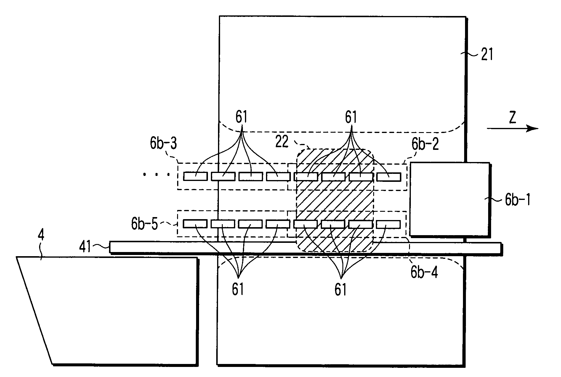
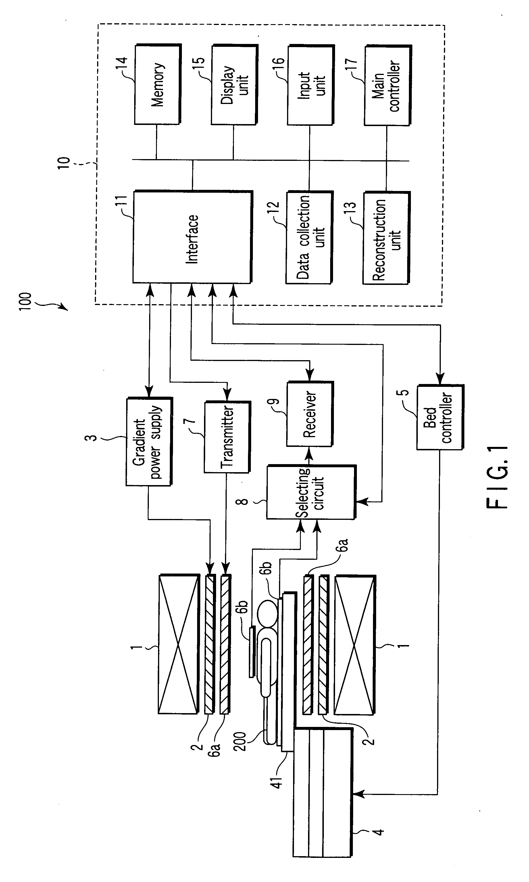
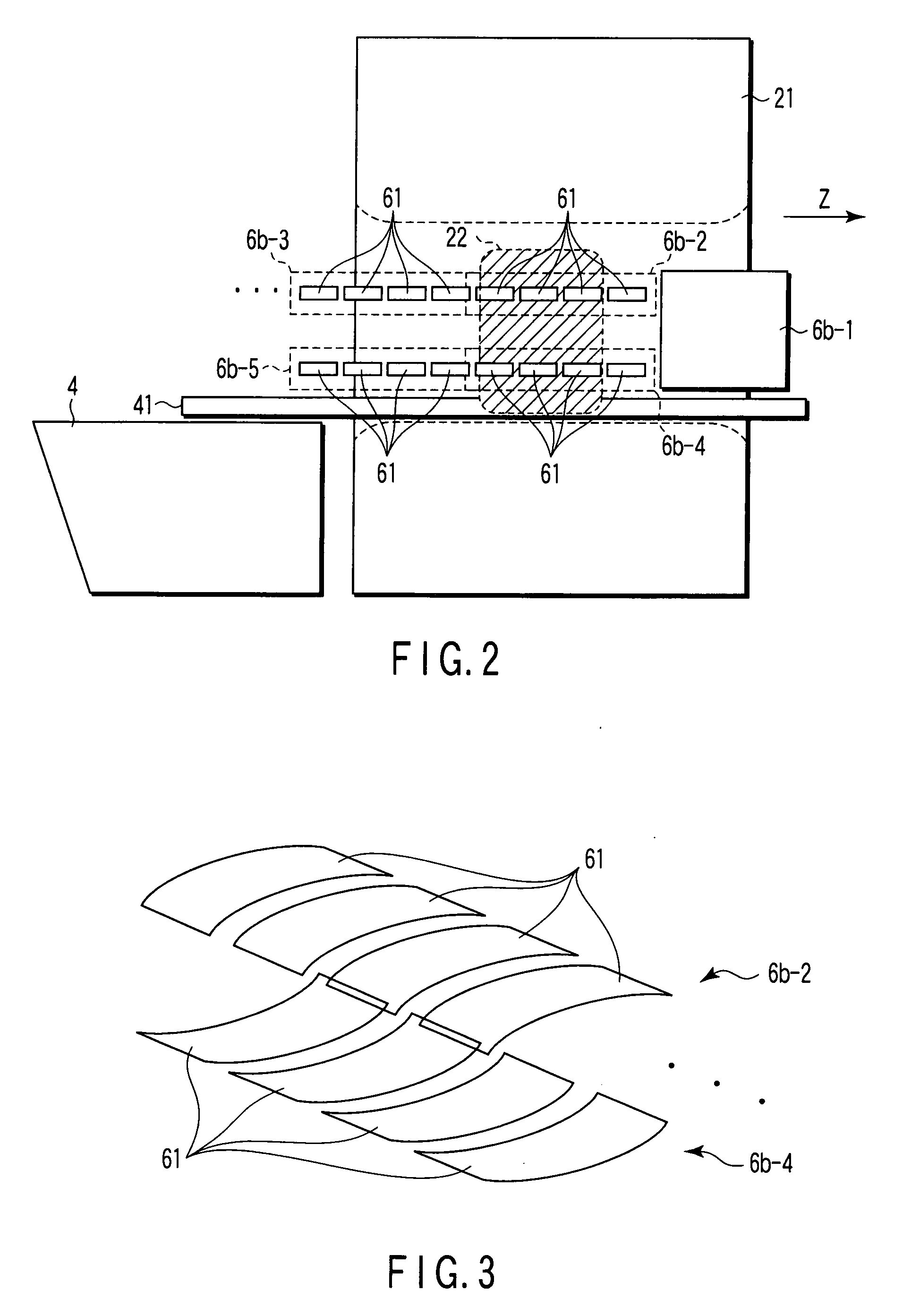
[0027]FIG. 1 is a block diagram illustrating the configuration of a magnetic resonance imaging (MRI) apparatus 100 according to the embodiment. The MRI apparatus 100 comprises a static field magnet 1, a gradient coil 2, a gradient power supply 3, a bed 4, a bed controller 5, RF coil units 6a and 6b, a transmitter 7, a selecting circuit 8, a receiver 9 and a computer system 10.

[0028]The static field magnet 1 is a hollow cylindrical member, and generates a uniform static magnetic field. The static field magnet 1 is, for example, a permanent magnet or a superconducting magnet.

[0029]The gradient coil 2 is also a hollow cylindrical member located inside the static field magnet 1. The gradient coil 2 is formed of three coils corresponding to three mutually perpendicular axes X, Y and Z. In the gradient coil 2, the three coils are individually supplied with a current from a gradient power sup...


PUM


Abstract

A magnetic resonance imaging apparatus includes an array coil in which a plurality of element coils are arranged to receive magnetic resonance signals from a subject, a calculation unit which calculates projection data for the element coils regarding an arrangement direction of the plurality of element coils on the basis of the plurality of magnetic resonance signals received by the plurality of element coils, and a determination unit which determines the positions of the plurality of element coils or the position of the array coil on the basis of the projection data for the plurality of element coils.

Description

CROSS-REFERENCE TO RELATED APPLICATIONS[0001]This application is based upon and claims the benefit of priority from prior Japanese Patent Application No. 2006-187145, filed Jul. 6, 2006, the entire contents of which are incorporated herein by reference.BACKGROUND OF THE INVENTION[0002]1. Field of the Invention[0003]The present invention relates to a magnetic resonance imaging apparatus which receives a magnetic resonance signal using an array coil formed by arranging a plurality of element coils.[0004]2. Description of the Related Art[0005]There is known a method of efficiently performing parallel imaging using an array coil formed by arranging a plurality of element coils.[0006]In this parallel imaging, performance can be enhanced by considering the position of the array coil. For example, in A. Reykowski, M. Blasche, “Mode Matrix—A Generalized Signal Combiner For Parallel Imaging Arrays,” ISMRM 2004, p. 1587, there is disclosed a technique for using “Mode Matrix” to efficiently pe...

Claims


Application Information

Patent Timeline
Patent Type & Authority Applications(United States)
IPC IPC(8): G01V3/00
CPCG01R33/3415G01R33/3664G01R33/56383G01R33/56375G01R33/5617
Inventor MACHIDA, YOSHIOICHINOSE, NOBUYASU
Owner TOSHIBA MEDICAL SYST CORP
Why Eureka
Try Eureka