
Fast Dynamic Gain Control In An Optical Fiber Amplifier

a dynamic gain control and optical fiber technology, applied in the direction of fibre transmission, laser details, electrical equipment, etc., can solve the problems of variable overall optical power in the transmission system, insufficient fastness of the approach, and inability to achieve fast dynamic gain control, etc., to achieve the effect of fast dynamic gain control

Active Publication Date: 2008-01-10
AMERICAN TELEPHONE & TELEGRAPH CO
View PDF15 Cites 6 Cited by
  • Summary
  • Abstract
  • Description
  • Claims
  • Application Information

AI Technical Summary

Benefits of technology

[0010] With another aspect of the invention, a dynamic gain control technique for both a forward-pumped distributed / discrete RFA and a backward-pumped discrete RFA enables the pump power adjustment to be completed in only one-step within a very short period of time (<<1 μs). For a forward-pumped RFA, the dynamic gain control technique enables the powers of the optical pumps to be adjusted synchronously with the input signal power and therefore perform fast dynamic gain control.

Problems solved by technology

In addition, accidental loss of channels due to fiber cut or from amplifier failure will also lead to variation of the overall optical power in the transmission system.
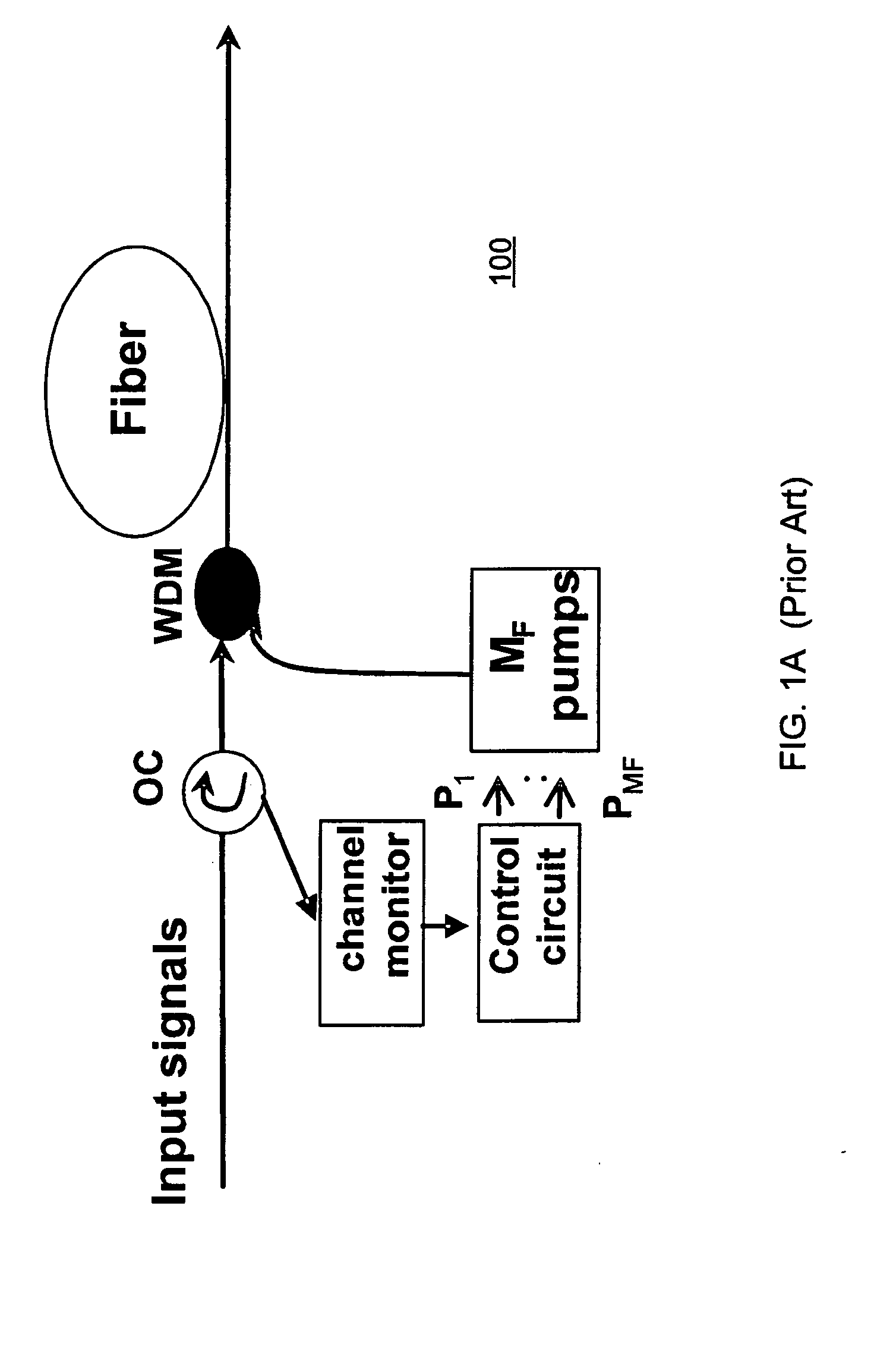
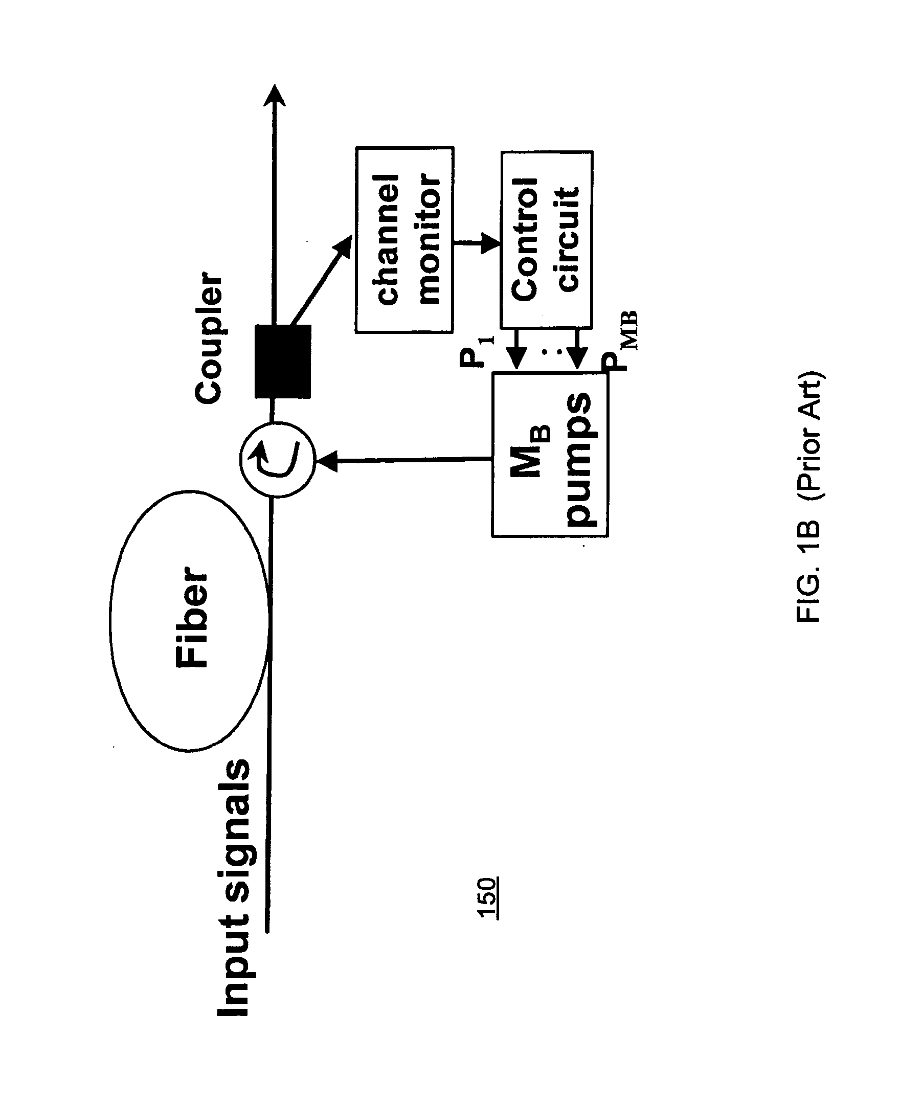
This approach is not typically fast enough for a forward-pumped RFA (either distributed or discrete), and many times even not fast enough for a backward-pumped discrete RFA, which typically has much shorter fiber length than a distributed RFA.
However this method introduces noise degradation and is not faster than the first method due to the same nature (closed feedback loop).
This not only increases its implementation complexity / cost, but also slows its capability of dynamic gain control.

Method used


Image

  • Fast Dynamic Gain Control In An Optical Fiber Amplifier
  • Fast Dynamic Gain Control In An Optical Fiber Amplifier
  • Fast Dynamic Gain Control In An Optical Fiber Amplifier

Examples


Embodiment Construction

[0041] In the following description of the various embodiments, reference is made to the accompanying drawings which form a part hereof, and in which is shown by way of illustration various embodiments in which the invention may be practiced. It is to be understood that other embodiments may be utilized and structural and functional modifications may be made without departing from the scope of the present invention.

[0042] Definitions for the following terms are included to facilitate an understanding of the detailed description. [0043] Optical fiber amplifier—a device to amplify an optical signal from an optical fiber facility without converting the signal from optical to electrical back again to optical energy. [0044] Optical pump—a shorter wavelength laser that is used to pump a length of optical fiber with energy to provide amplification of one or more longer wavelengths.

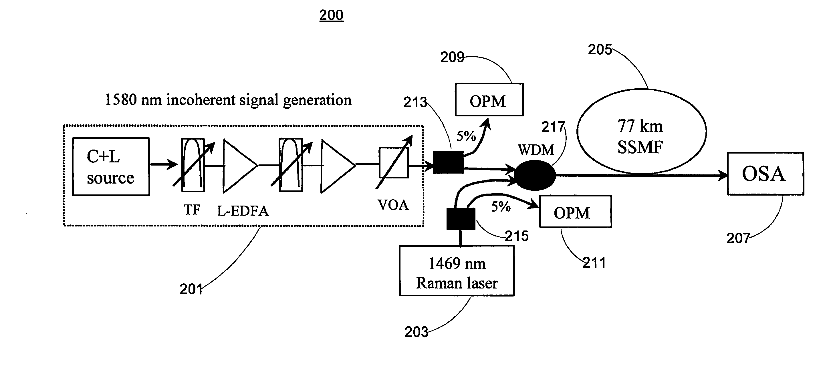
[0045]FIG. 2 shows an experimental setup 200 for a forward-pumped Raman fiber amplifier in accordance with a...


PUM


Abstract

The present invention provides methods and apparatuses for controlling a gain of an optical fiber amplifier. Gain circuitry operates in an opened loop configuration and uses a predetermined function relating a power variation of at least one wavelength region with a pump power adjustment for at least one optical pump. Two approximate linear relationships between the input signal power variations and the required pump power adjustments are utilized in controlling the Raman fiber amplifier. Each approximate linear relationship includes at least one linear coefficient that relates a power variation for a specific wavelength region and a power adjustment of a specific Raman pump. The dynamic gain control technique is applicable to an Erbium-doped fiber / waveguide amplifier. Also, a dynamic gain control technique controls a backward-pumped Raman amplifier, in which the power variation is determined at one geographical location and the optical pumps are controlled at another geographical location.

Description

[0001] This application is a continuation of common-owned, co-pending U.S. application Ser. No. 11 / 273,868 (“Fast dynamic gain control in an optical fiber amplifier”) filed on Nov. 15, 2005 naming Xiang Zhou and Martin Birk and claiming priority to provisional U.S. application Ser. No. 60 / 656,111 (“Fast dynamic gain control in an optical fiber amplifier”), filed Feb. 24, 2005, the contents of which are incorporated herein in their entirety.FIELD OF THE INVENTION [0002] The present invention relates to dynamically controlling the gain of an optical fiber amplifier. BACKGROUND OF THE INVENTION [0003] Distributed Raman fiber amplification has been proven to be a powerful technique to improve the optical signal to noise ratio (OSNR) margin of long haul wavelength-division multiplexing (WDM) system. The discrete Raman fiber amplifier is also an effective method to compensate the loss of the dispersion fiber module and / or provide extra bandwidth. A Raman fiber amplifier can be configured ...

Claims


Application Information

Patent Timeline
Patent Type & Authority Applications(United States)
IPC IPC(8): H01S3/091
CPCH01S3/06754H01S3/094096H01S3/10015H04B10/296H01S2301/04H04B10/2916H01S3/302
Inventor ZHOU, XIANGBIRK, MARTIN
Owner AMERICAN TELEPHONE & TELEGRAPH CO
Learn More