
Method of Producing Polarizing Plate, Polarizing Plate, Optical Film, and Image Display Therewith

a technology of polarizing plates and optical films, applied in the direction of instruments, polarising elements, optical elements, etc., can solve the problems of interfering with the upsizing of polarizing plates, and achieve the effect of large effective width, large area yield, and large image displays

Inactive Publication Date: 2008-01-10
NITTO DENKO CORP
View PDF7 Cites 23 Cited by
  • Summary
  • Abstract
  • Description
  • Claims
  • Application Information

AI Technical Summary

Benefits of technology

[0014] As described above, at least one edge with respect to the direction of the width of the polarizing film is removed by cutting after the preparation of the polarizing film and before the bonding of the protective film, in the method of producing the polarizing plate according to the invention, so that the occurrence of defects at the edge with respect to the direction of the width of the polarizing film can be suppressed. It is on the assumption that the defects which would otherwise be caused by thickness unevenness occurring at the edge of the polarizing film during the bonding is removed before the bonding. Thus the protective film can be free from defects up to the edge in the width direction, so that a large size polarizing plate with a large effective width can be provided. In addition, by the use of the polarizing plate, the area yield with respect to general-purpose sizes (such as a size of 32 inches) can be increased, and larger-sized image displays can be provided.
[0015] According to the invention, at least one edge with respect to the direction of the width of the polarizing film is removed by cutting after the preparation of the polarizing film and before the bonding of the protective film, so that a protective film with any necessary width can be used depending on the effective width of the polarizing film. Thus, the amount of the protective film waste can be reduced, and the protective film can be effectively utilized. Conventionally, if the width of the polarizing film is wide, it will be difficult to select or prepare a protective film having a width suitable for the width of the polarizing film. According to the invention, however, it will be easy to select or prepare a suitable protective film depending on the width of the polarizing film. Because of a high occupancy of the protective film in the polarizing plate, the production method of the invention can significantly contribute to the effective use of the protective film and can be significantly effective for environmental protection by reducing wastes.

Problems solved by technology

Thus, such methods have the problem of interfering with upsizing of polarizing plates.

Method used


Image

  • Method of Producing Polarizing Plate, Polarizing Plate, Optical Film, and Image Display Therewith
  • Method of Producing Polarizing Plate, Polarizing Plate, Optical Film, and Image Display Therewith

Examples


example 1

[0063] An 80 μm-thick polyvinyl alcohol (PVA) film (2400 in degree of polymerization, manufactured by Kuraray Co., Ltd.) with a length of 2700 mm in its width direction was used. While kept under a tension, the PVA film was immersed in pure water at 30° C. for 60 seconds, and stretched to a ratio of 3 times in an aqueous 0.3% by weight iodine solution at 30° C. The PVA film was then stretched in an aqueous solution of 4% by weight boric acid and 3% by weight potassium iodide at 60° C. in such a manner that the total stretch ratio reached 6 times. The stretched PVA film was immersed in an aqueous 3.5% by weight potassium iodide solution at 30° C. for 10 seconds and then dried at 30° C. for four minutes while the tension of the film was maintained, so that a polarizing film having a length of 1340 mm in its width direction was obtained. A 40 mm-wide edge portion was removed by cutting from each of both edges of the resulting polarizing film with respect to the width direction, so that...

example 2

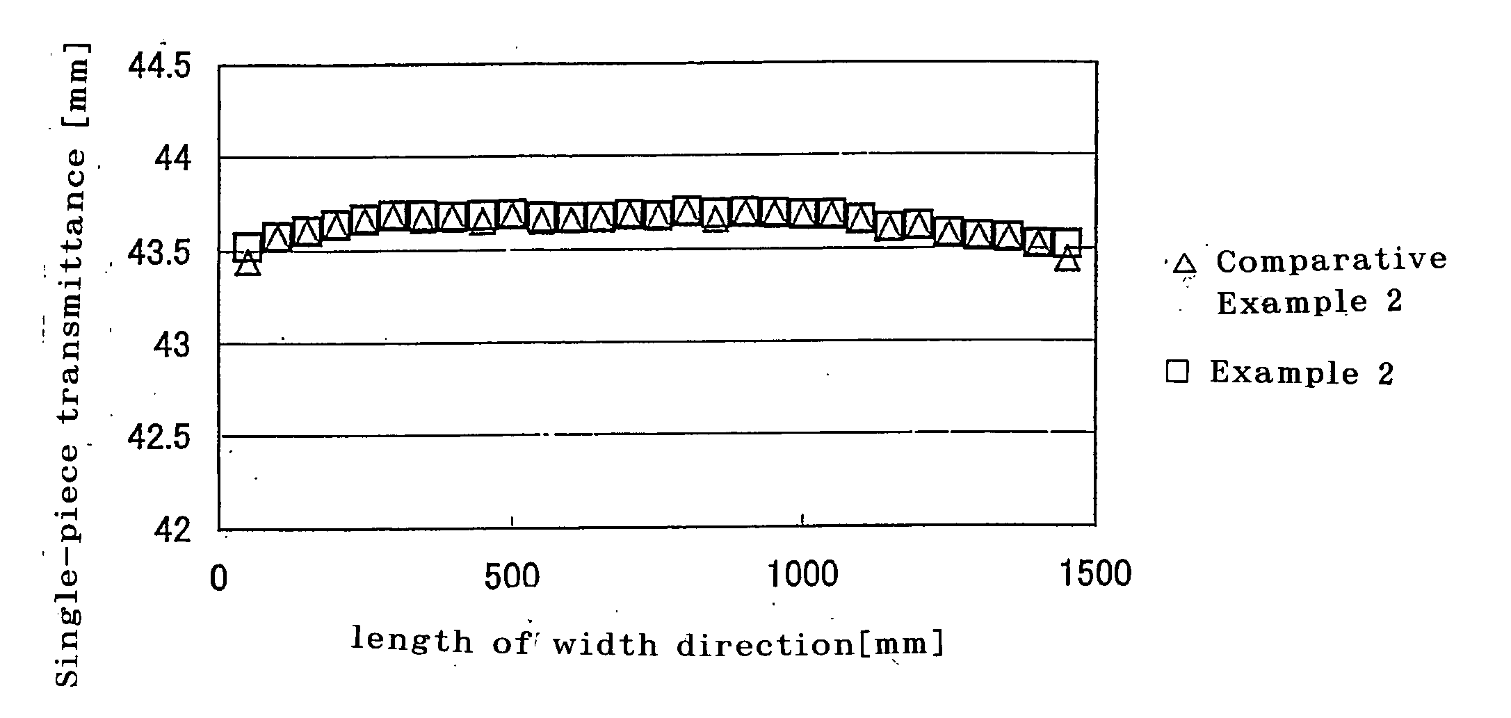
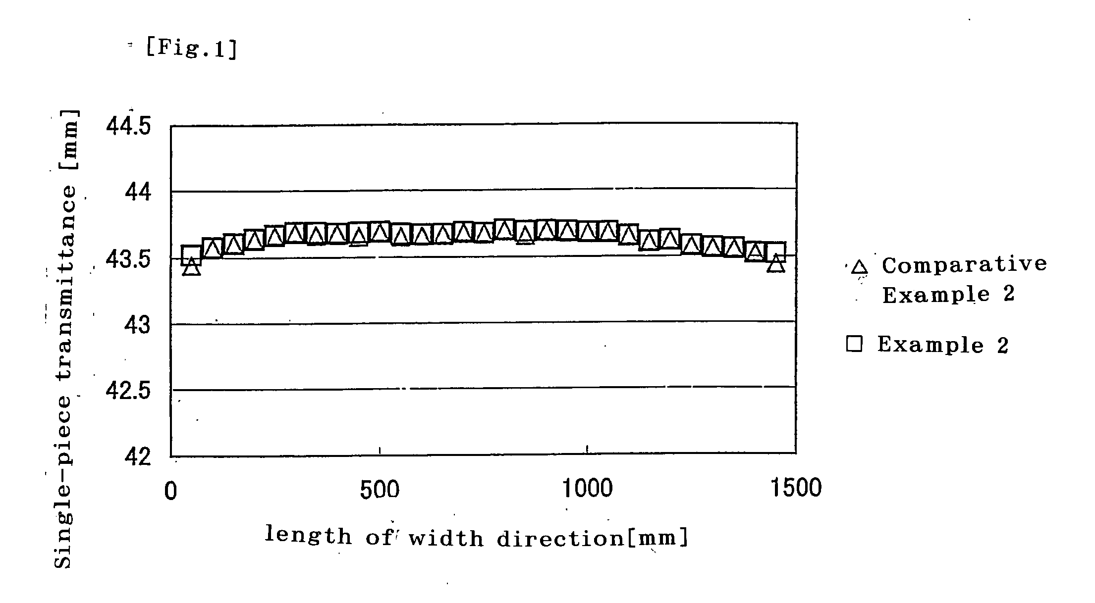
[0064] A polarizing film having a length of 1540 mm in its width direction was prepared using the process of Example 1 except that a 75 μm-thick polyvinyl alcohol (PVA) film (2400 in degree of polymerization, manufactured by Kuraray Co., Ltd.) with a length of 3100 mm in its width direction was alternatively used. A 40 mm-wide edge portion was removed by cutting from each of both edges of the resulting polarizing film with respect to the width direction, so that a polarizing film having a length of 1460 mm in its width direction was obtained. After removing by cutting, triacetyl cellulose (TAC) films (TDY80UL manufactured by Fuji Photo Film Co., Ltd.) each with a length of 1475 mm in the width direction were bonded to both sides of the polarizing film by the use of an adhesive mainly composed of an aqueous solution of 5% completely saponified polyvinyl alcohol. The resulting laminate was dried at 70° C. for four minutes to give a polarizing plate.


PUM

PropertyMeasurementUnit
widthaaaaaaaaaa
widthaaaaaaaaaa
widthaaaaaaaaaa

Abstract

A method of producing a polarizing plate of the present invention comprises the steps of: bonding a protective film to at least one side of a polarizing film that is produced through at least uniaxial stretching and has an absorption axis in the uniaxial stretching direction, and removing by cutting at least one of the edges of the polarizing film that are substantially parallel to the direction of the absorption axis before the bonding the protective film. The method widen the effective width of the polarizing plate, and a large size polarizing plate was obtained.

Description

TECHNICAL FIELD [0001] The invention relates to a method of producing a polarizing plate for use in image displays such as liquid crystal displays (LCDs) and electroluminescence displays (ELDs). The invention also relates to a polarizing plate produced by the method, an optical film having the polarizing plate, and an image display having any of them. BACKGROUND ART [0002] Polarizing plates for use in image displays, particularly liquid crystal displays, are required to have high transmittance, high degree of polarization, and in-plane uniformity at the same time in order to provide bright images with good color reproducibility. Such polarizing plates are generally produced by a process including the steps of dyeing a polymer film such as a polyvinyl alcohol (PVA) film with a dichroic material such as iodine and a dichroic dye to form a polarizing film and then bonding, to both sides of the polarizing film, protective films that are each composed of a polymer film such as a triacety...

Claims


Application Information

Patent Timeline
Patent Type & Authority Applications(United States)
IPC IPC(8): G02B5/30B29D7/01
CPCB29D11/00634G02F1/133528G02B5/3033G02B5/30
Inventor MIZUSHIMA, HIROAKISAIKI, YUUJIKAMEYAMA, TADAYUKIWADA, MORIMASANAGANO, SHINOBU
Owner NITTO DENKO CORP
Learn More