Protection circuit for an input stage, and respective circuit arrangement

a protection circuit and input stage technology, applied in the protection circuit arrangement of amplifiers, capacitors, low frequency amplifiers, etc., can solve the problems of insufficient protection of zener diodes, schottky diodes, and zener diodes specially designed for overvoltage protection, so as to achieve the effect of considerably improving the protection effect of the array

Inactive Publication Date: 2008-01-10
THOMSON LICENSING SA
View PDF6 Cites 2 Cited by
  • Summary
  • Abstract
  • Description
  • Claims
  • Application Information

AI Technical Summary

Benefits of technology

[0006] However, the protective effect of this array can be considerably improved through the use of an additional capacitance, especially of a capacitor, parallel to the Zener diode array. The Zener diode array apparently needs a certain amount of time to complete the circuit, and the initial part of the voltage pulse can be intercepted by the capacitor in parallel until the array is enabled. The capacitance value of this capacitor is, for example, in the order of magnitude of the capacitance value of the coupling capacitor on the input side.

Problems solved by technology

Investigations have shown that even a TVS Zener diode array specially designed for overvoltage protection, with four Zener diodes and connected on the input side via a Schottky diode, is possibly not sufficient when a coupling capacitor is accidentally short circuited.

Method used


Image

  • Protection circuit for an input stage, and respective circuit arrangement
  • Protection circuit for an input stage, and respective circuit arrangement

Examples


Embodiment Construction

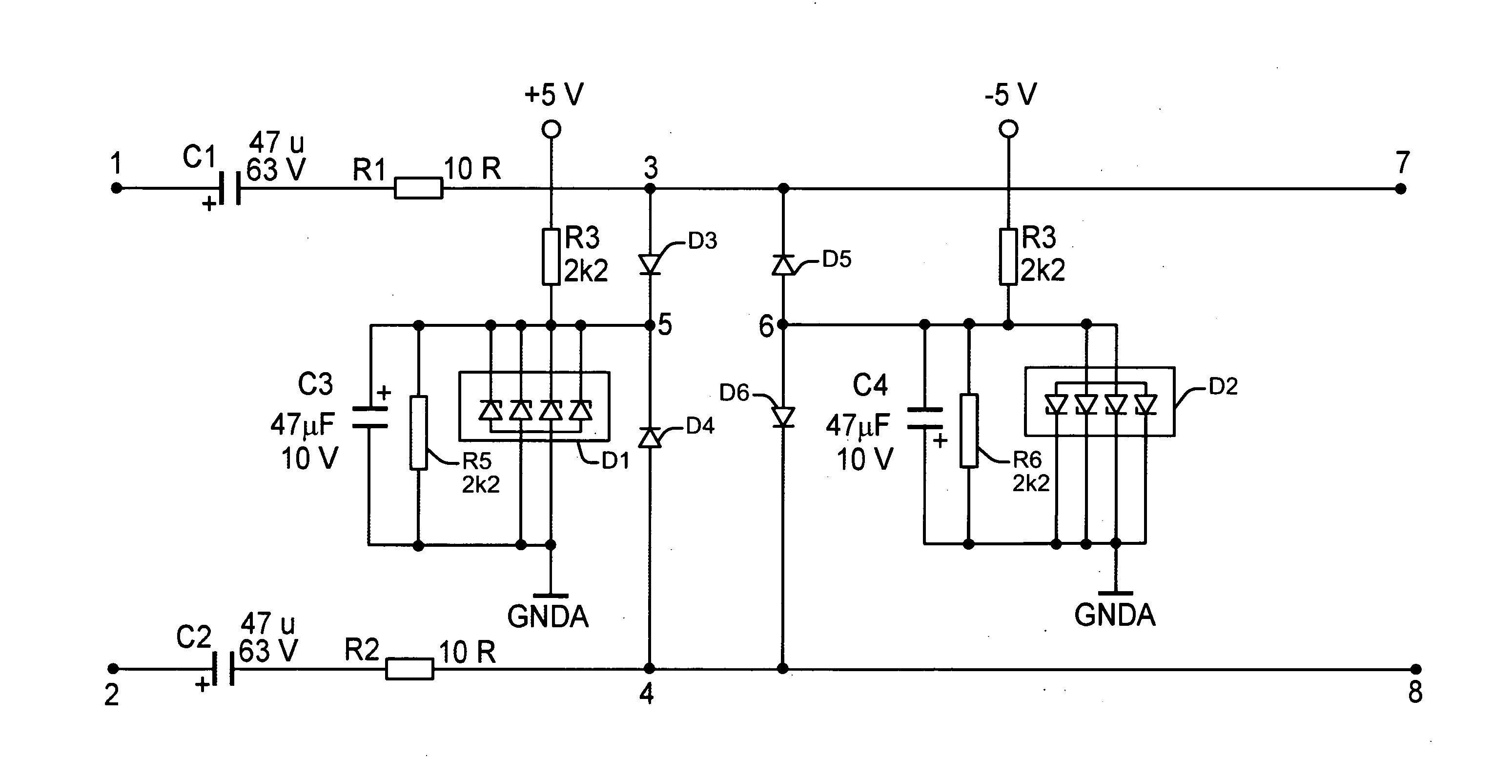
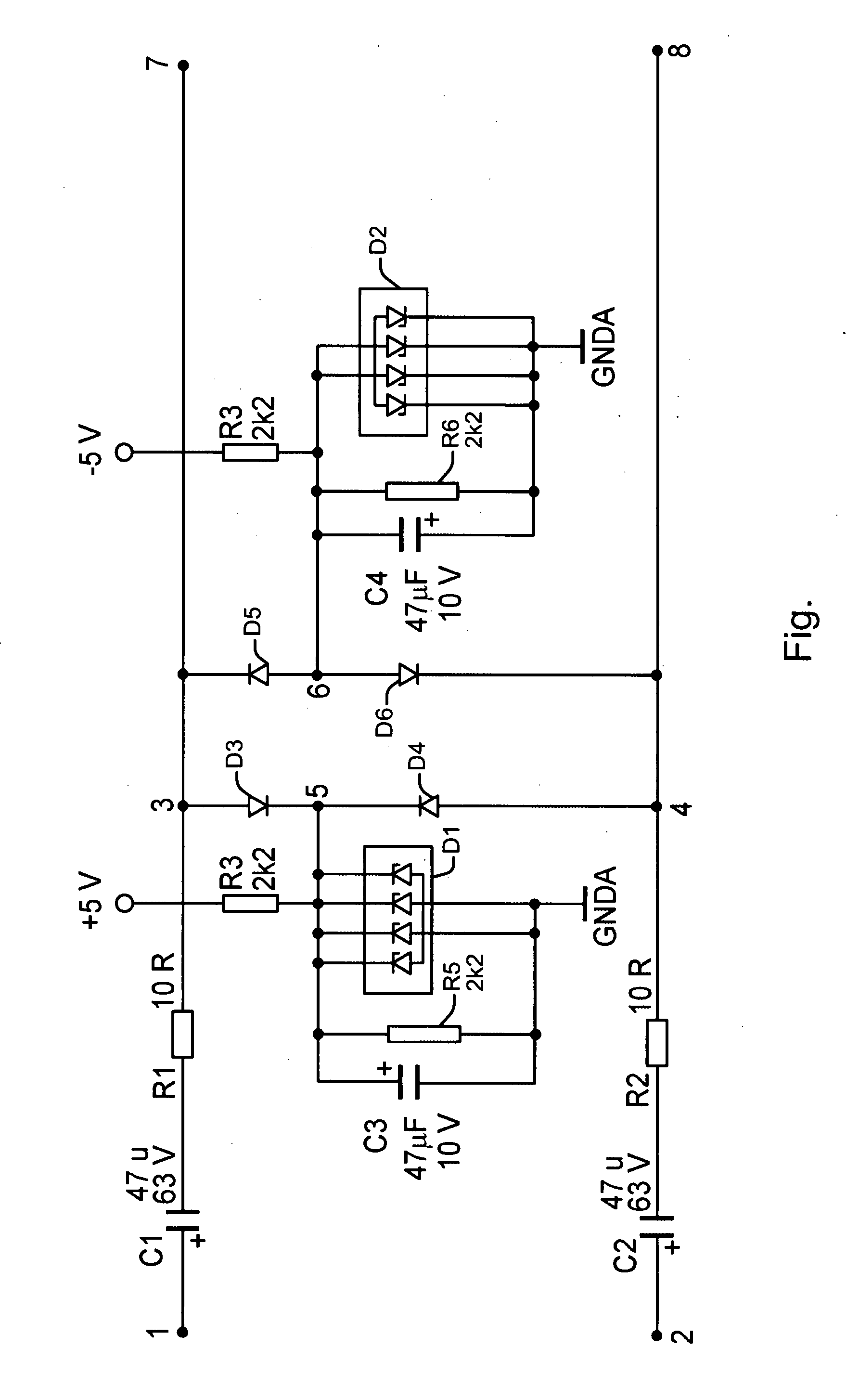
[0010] The FIGURE shows a circuit arrangement with an input stage, comprising a symmetrical input with connections 1 and 2 as well as coupling capacitors C1, C2. The input stage is connected in series with an integrated preamplifier, not shown, which comprises two connections 7 and 8 on the input side. The preamplifier is, for example, a microphone preamplifier of the type PGA2500, available from Texas Instruments. This IC must be operated with two supply voltages of a maximum of + / −5 volt. The inputs of this preamplifier are sensitive to electrostatic discharges and the input signals must, in particular, not be essentially above or, respectively, below the supply voltages used.

[0011] The inputs 7, 8 of the preamplifier are a.c. coupled with the inputs 1 and 2 by the coupling capacitors C1, C2, and the input stage can therefore be connected with a microphone which needs its own supply voltage. Capacitor microphones in particular need a supply voltage of +48 volt. Since microphone p...


PUM


Abstract

The protection circuit comprises a Zener diode which is connected via a diode to a coupling capacitor of an input stage, wherein a capacitor is arranged in parallel to the Zener diode. The capacitor is, for example, a tantalum electrolytic capacitor with a capacitance value which is in the range of the value of the coupling capacitor. The protection circuit can be used, in particular, for the protection of sensitive microphone preamplifiers which are connected, via the coupling capacitor, to a capacitor microphone.

Description

BACKGROUND OF THE INVENTION [0001] This invention relates to a protection circuit with a Zener diode and a diode being connected to an input stage, and to a circuit arrangement comprising a respective protection circuit. A protection circuit of this type is used, for example, for preamplifiers which have highly-sensitive inputs to protect them from ESD and other discharge voltage pulses, for example, when a capacitor microphone is connected to the input stage. [0002] It is known that microphones, especially capacitor microphones, need an operating voltage, 48 volt for example. For capacitor microphones, this operating voltage is also known as “phantom power”. This operating voltage is isolated via two coupling capacitors from the inputs of the preamplifier. However, to ensure low-frequency rendition to below 20 Hz, the two capacitors must have a relatively high capacitance, 47 microfarad each, for example. Due to this magnitude and the applied voltage, the coupling capacitors accord...

Claims


Application Information

Patent Timeline
Patent Type & Authority Applications(United States)
IPC IPC(8): H02H9/04H02H7/16
CPCH02H9/04H04R3/007H03F3/181H03F1/52
Inventor GRIES, ULRICHSCHREIBER, ULRICH
Owner THOMSON LICENSING SA
Why Eureka
Try Eureka