
Cardiac monitoring system

a monitoring system and cardiac catheter technology, applied in the field of cardiac catheter monitoring system, can solve the problems of fragile signal with low signal to noise ratio, inability to accurately model the bioimpedance response of subjects, and the increasing burden of cardiovascular diseases around the world

Active Publication Date: 2008-01-10
IMPEDANCE CARDIOLOGY SYST +1
View PDF44 Cites 82 Cited by
  • Summary
  • Abstract
  • Description
  • Claims
  • Application Information

AI Technical Summary

Benefits of technology

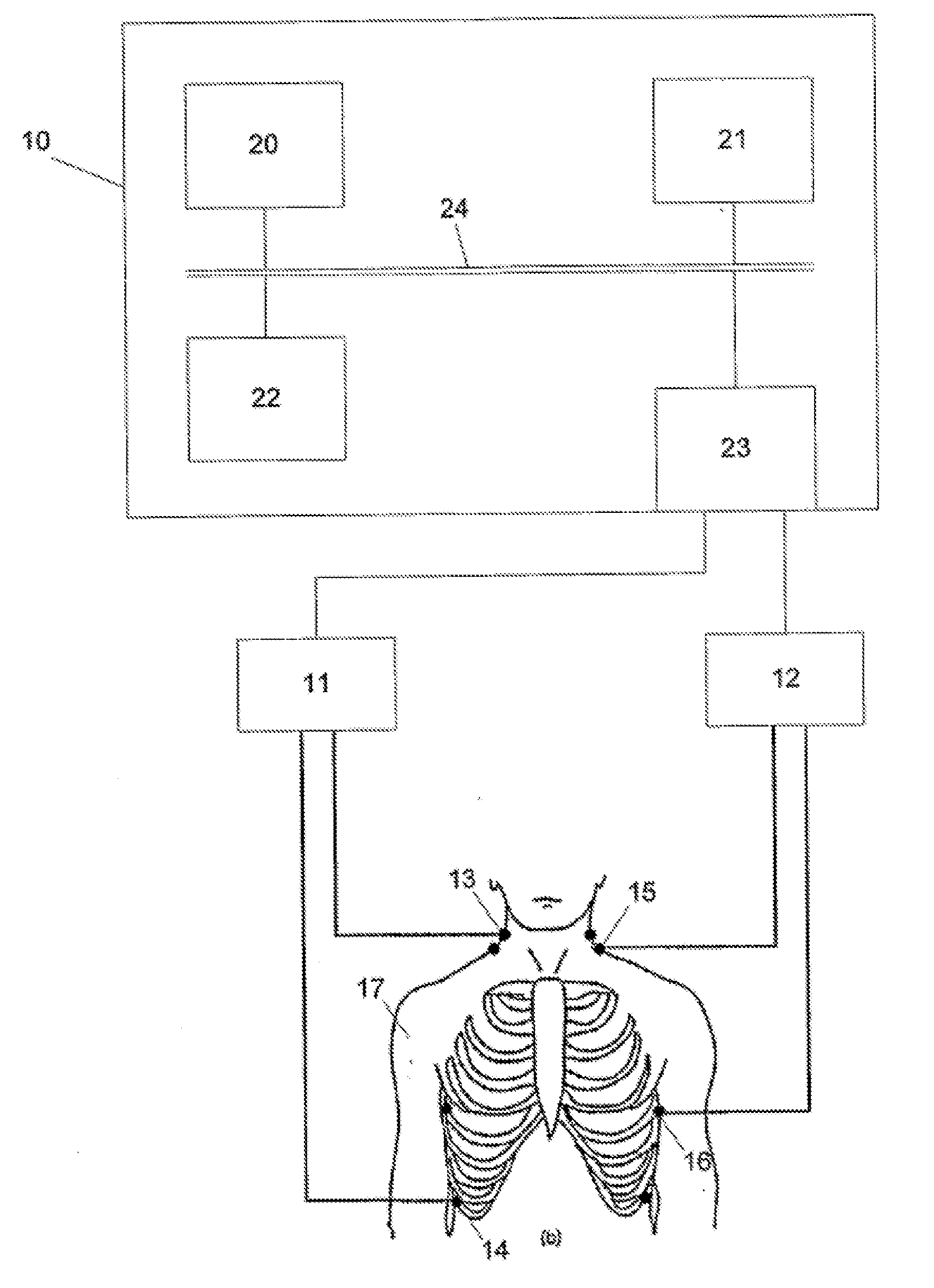
[0023] Also described herein are systems for analyzing cardiac function in a subject. These systems may include a plurality of electrodes configured to be attached to a subject, and a processor connected to the plurality of electrodes. The processor may be configured to control the application of an electrical signal having a plurality of frequencies to the subject, receive an electrical signal from the subject in response to the applied signal, determine a characteristic frequency by comparing the applied and received electrical signals, determine at least one component of the impedance at the characteristic frequency, and determine a measure of cardiac function using the at least one component of the impedance determined at the characteristic frequency. In some variations, the system also includes a signal generator coupled to processor for generating the electrical signals applied to the subject. The systems may also include one or more sensors for detecting the electrical signals from the subject in response to the applied electrical signals.
[0024] In some variations, the system may also include processing logic for determining the measure of cardiac output by multiplying the at least one component of the impedance (e.g., reactance, phase shift) by one or more constants including constants based on the subject's physical characteristics. The processing logic may be implemented by software, hardware, or any combination of these. Thus, the processor may be a microprocessor configured to execute the processing logic.
[0025] Any of the systems described herein may also include one or more input devices in communication with the processor for entering at least some of the subject's physical characteristics. For example, the systems may include a keypad, mouse, memory, wireless connection or the like for receiving input. Physical characteristics may include height, gender, weight, pulse rate, age, ethnicity, etc.

Problems solved by technology

The treatment of coronary heart disease and other cardiovascular diseases therefore represents and increasingly large health and economic burden throughout the world in the coming years.
The changes in impedance due to the cardiac cycle are a relatively small (0.5%) fraction of the baseline impedance, which leads to a very fragile signal with a low signal to noise ratio.
A further issue in WO2004 / 032738 is that the process determines the impedance at zero applied frequency using the “Cole model”.
However, again this assumes idealised behaviour of the system, and consequently does not accurately model a subject's bioimpedance response.
Consequently cardiac parameters determined using these techniques tend to be of only limited accuracy.

Method used


Image

  • Cardiac monitoring system
  • Cardiac monitoring system
  • Cardiac monitoring system

Examples


Embodiment Construction

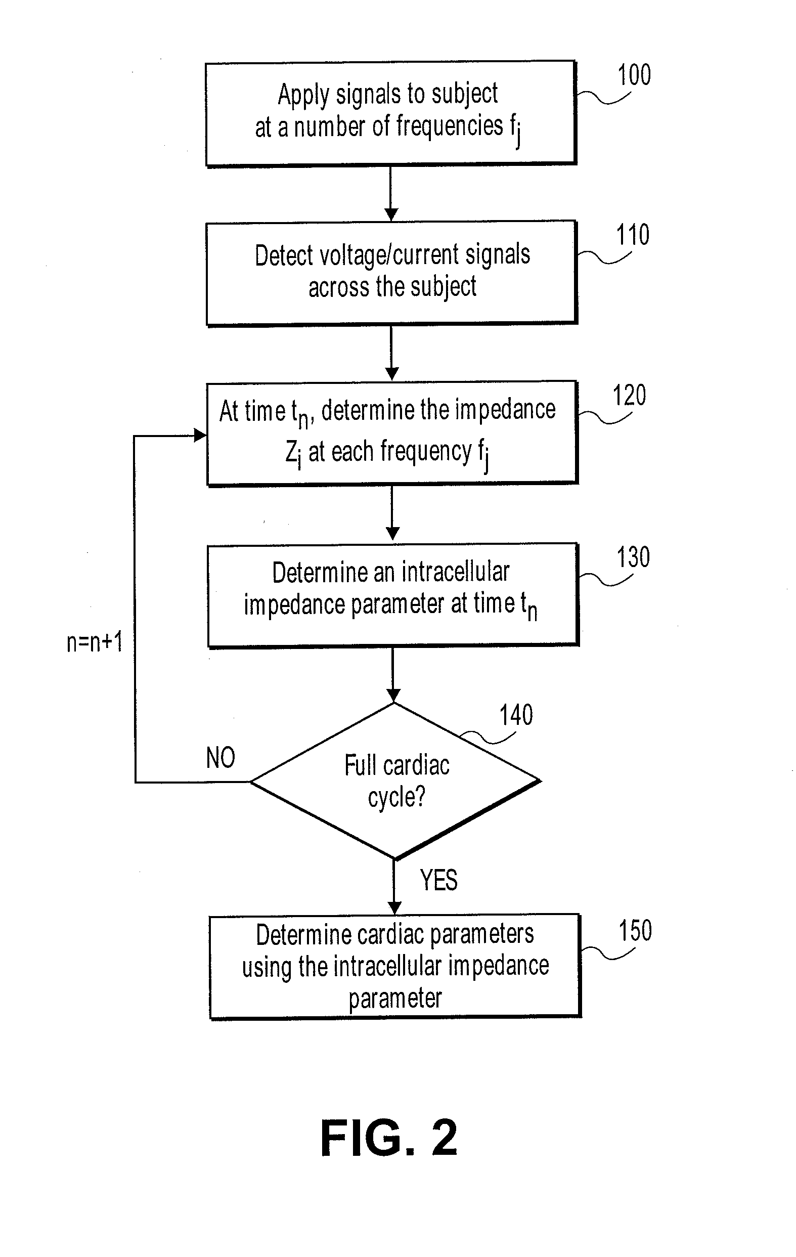
[0037] An example of a process for determining parameters of cardiac function relating to a subject is described with reference to FIG. 2.

[0038] In particular at step 100, alternating electrical signals are applied to the subject at a number of different frequencies fi, with electrical signals across the subject being detected at each of the respective fi, at step 110. The nature of the signals applied and detected will depend on the implementation as will be described below.

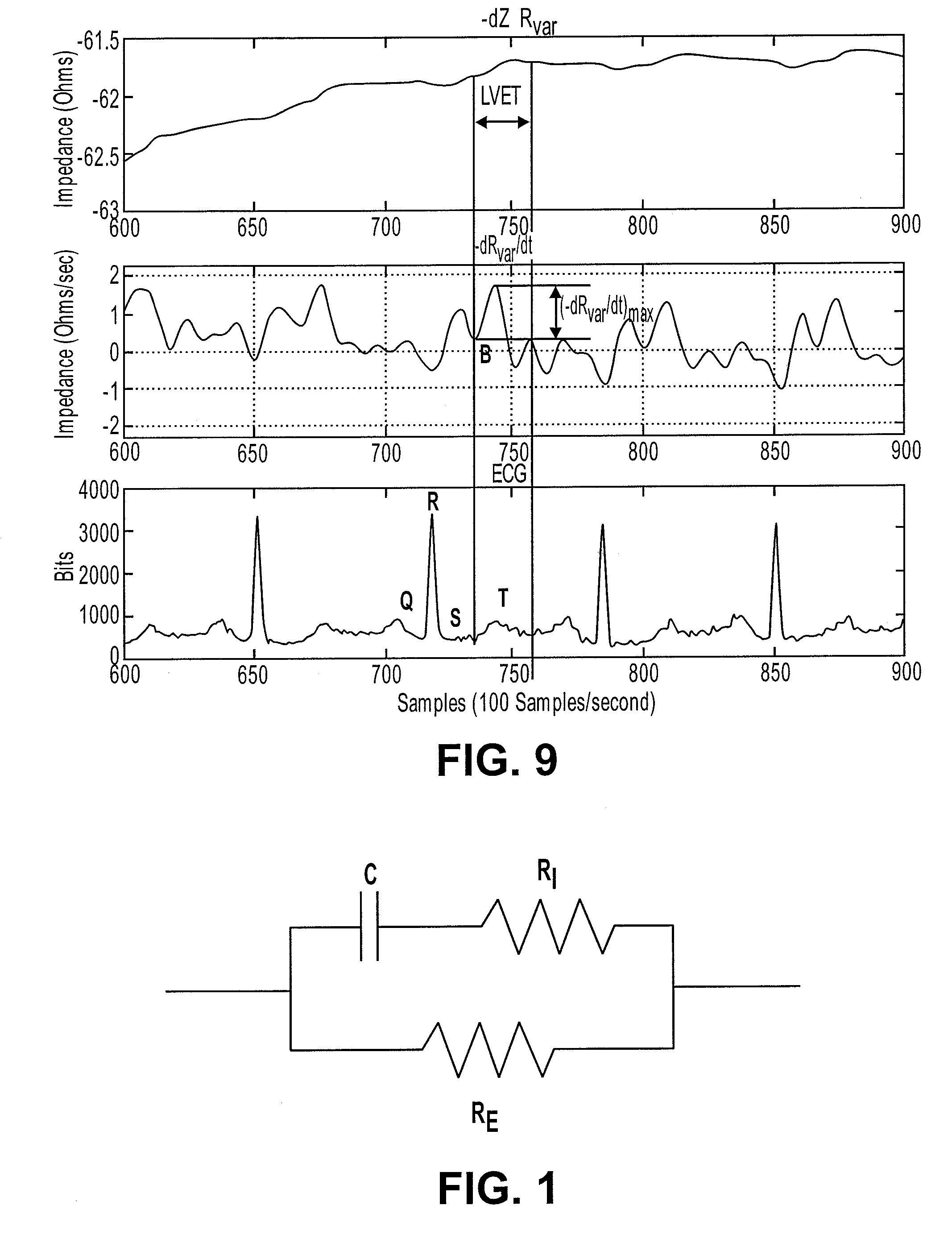
[0039] At step 120, at a first time instance tn the impedance Zi at each frequency fi is determined. At step 130, the impedance is used to determine an intracellular impedance parameter at the time tn. In one example, this is achieved utilising an appropriate model, such as a CPE (constant phase element) model, which will be described in more detail below.

[0040] This is performed for a number of sequential time instance tn, tn+1, tn+2 until it is determined that a complete cardiac cycle has been analyzed at s...


PUM


Abstract

A method of analyzing cardiac functions in a subject using a processing system is described. The method may include applying one or more electrical signals having a plurality of frequencies to the subject and detecting a response to the applied one or more signals from the subject. A characteristic frequency can then be determined from the applied and received signals, and at least one component of the impedance (e.g., reactance, phase shift) can be measured at the characteristic frequency. Thus, the impedance or a component of impedance at a characteristic frequency can be determined for a number of sequential time instances. A new characteristic frequency may be determined within a cardiac cycle (e.g., with each sequential time instant) or the same characteristic frequency may be used throughout the cardiac cycle during which instantaneous values of impedance (or a component of impedance) are determined. These instantaneous values may be used to determine one or more indicia of cardiac function.

Description

CROSS REFERENCE TO RELATED APPLICATIONS [0001] This application is the continuation in part of U.S. patent application Ser. No. 11 / 629,804, filed Jun. 15, 2006, which is a National Stage of International Application No. PCT / AU05 / 000893, filed Jun. 21, 2005, which application claims priority to Australian Application No. 2004903334, filed Jun. 21, 2004 and Australian Application No. 2004906181, filed Oct. 26, 2004. All of these applications are herein incorporated by reference in their entirety.BACKGROUND OF THE INVENTION [0002] The present invention relates to methods and apparatuses for monitoring biological parameters, and in particular to a method and apparatus for measuring cardiac function in a subject using bioelectric impedance or components of bioelectric impedance. [0003] The reference to any prior art in this specification is not, and should not be taken as, an acknowledgment or any form of suggestion that the prior art forms part of the common general knowledge. [0004] It...

Claims


Application Information

Patent Timeline
Patent Type & Authority Applications(United States)
IPC IPC(8): A61B5/053A61B5/02
CPCA61B5/02028A61B5/0535A61B5/053A61B5/029A61B5/0295
Inventor CHETHAM, SCOTT MATTHEW
Owner IMPEDANCE CARDIOLOGY SYST
Learn More