Needleless access vial

Inactive Publication Date: 2008-01-10
HALKEY ROBERTS CORP
View PDF99 Cites 60 Cited by
  • Summary
  • Abstract
  • Description
  • Claims
  • Application Information

AI Technical Summary

Benefits of technology

[0019] The invention incorporates the needleless functionality directly into the pharmaceutical vial packaging, thereby eliminating the need for a separate “add-on” vial access cap as taught by the prior art. Yet, the invention also allows for the use of a needle if required.
[0020] The needleless access vial of the invention includes an internal luer configuration that allows the fitting of a syringe having a standard slip luer connection thereto. Moreover, the valve element of the invention is configured to allow repeated access. The needleless access vial is therefore not limited to single use vials. Finally, the needle less access vial is co

Problems solved by technology

Obviously the use of the needle on syringe presents the continual risk of injury and infectious contamination to the clinician, as well as requiring appropriate disposal of the needle after use.
The integral spike on the “add-on” vial cap access device suffers from the distance it must protrude past the elostomeric vial seal, rendering it incapable of permitting extraction of the entire pharmaceutical contents of the vial.
This results in waste from either the practice of over-filling the vials by pharmaceutical packagers, or by disposal of unused contents of the vial by the clinician.
Use of the separate vial access cap attachment, results in waste from its single use on each vial, or the unacceptable ri

Method used


Image

  • Needleless access vial
  • Needleless access vial
  • Needleless access vial

Examples


first embodiment

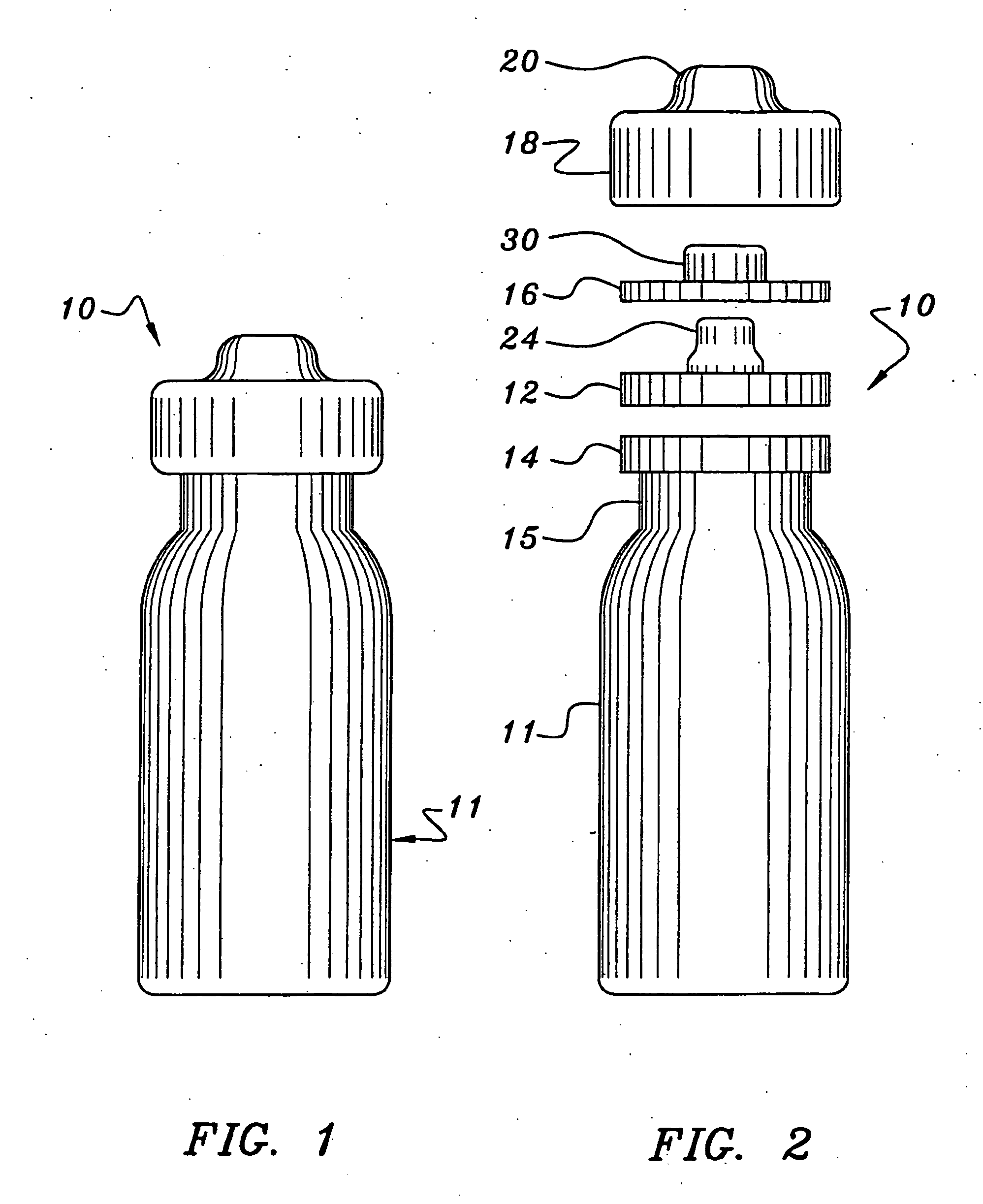
[0034] As shown in FIGS. 1-4, the needleless access vial 10 of the invention comprises a pharmaceutical vial 11 sealed by a valve element 12.

[0035] As shown in FIG. 2, the needleless access vial 10 comprises a valve element 12 seated on an annular ring 14 integrally formed on the upper neck 15 of the vial 11. The vial 10 further comprises a valve body 16 positioned on the valve element 12. A retainer 18 is configured to be mounted over the sandwiched valve body 16, valve element 12 and annular ring 14 and then crimped under the annular ring 14 of the vial 11 to secure such components together. The upper dome 20 of the retainer 18 is perforated about its periphery allowing it to be easily removed to expose the valve body 16.

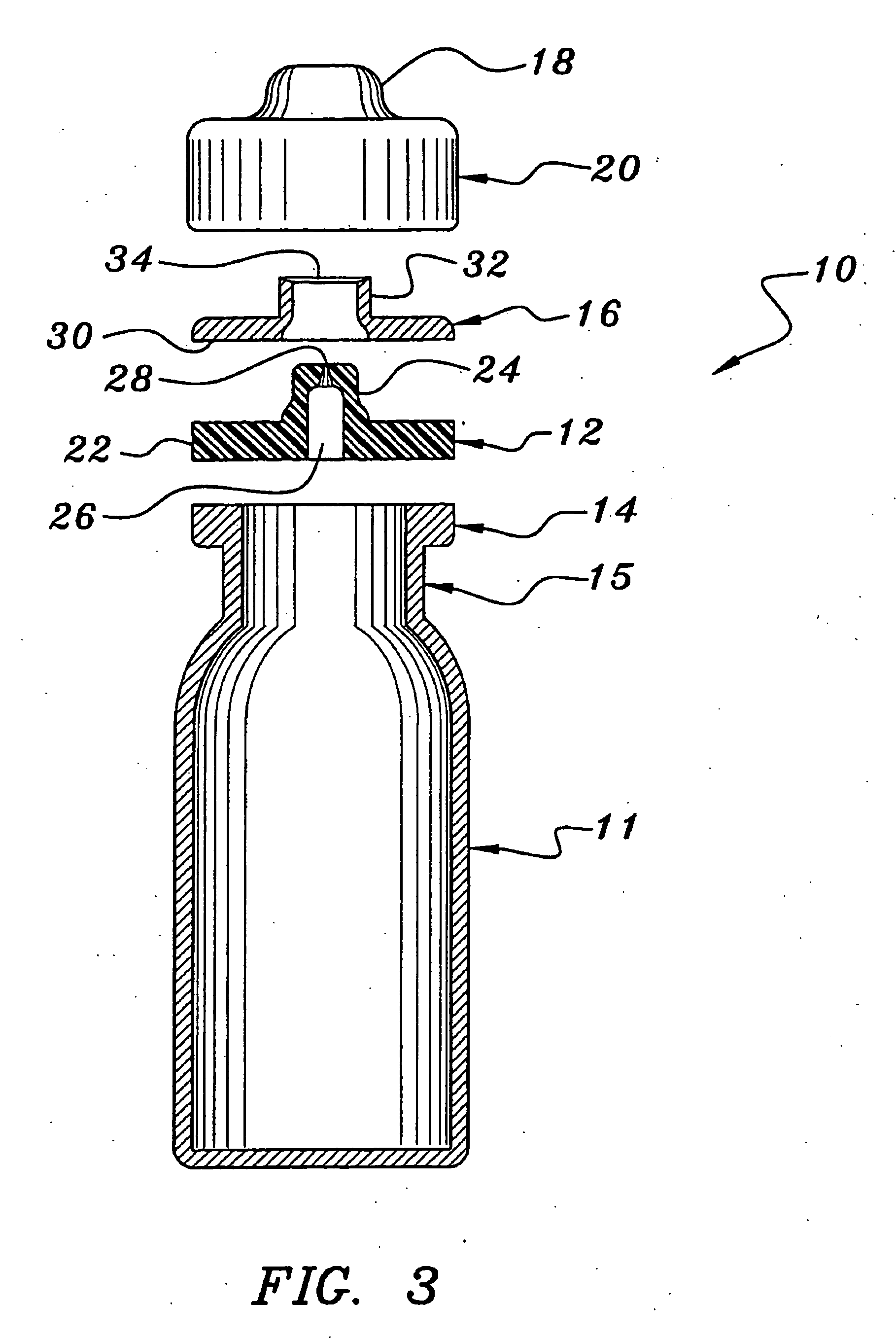
[0036] As shown in FIGS. 3 and 4, the valve element 12 comprises a disk portion 22 having an integral upstanding concentric center stem 24. The stem 24 includes a lower cylindrical portion 24LC, a frustro-conical portion 24F and an upper cylindrical portion 24UC....

second embodiment

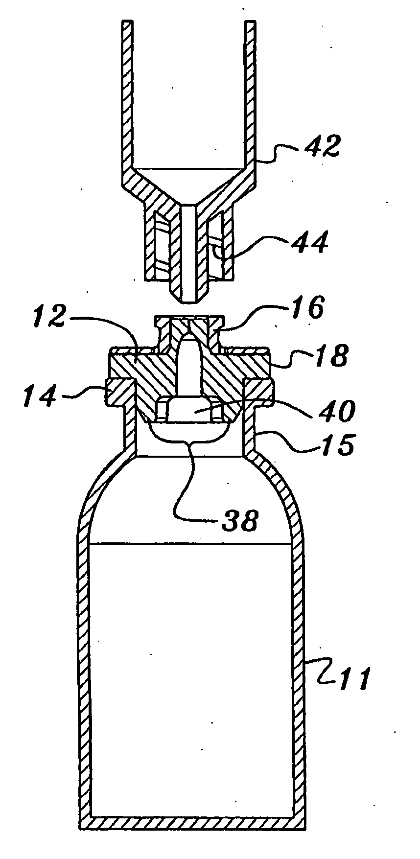
[0047] As best shown in FIG. 7, in addition to the upstanding boss portion 32 of the valve element 12, the vial 10 comprises a downwardly-extending boss 36 that includes an outer diameter approximately equal to or slightly greater than the inner diameter of the neck of the vial 11. Further, the boss 36 comprises opposing arcuate legs 38 defined by transverse slot 40. Preferably, each leg 38 includes an upper cylindrical portion 38UC of the same diameter of the boss portion 36 and an lower inwardly-tapered portion 38T. Upon insertion of the neck of the syringe to force the stem 24 inwardly, the boss 36 provides increased sealing with the lumen of the neck of the vial 11 whereas, due to the taper 38T, the legs 38 are allowed to move radially outwardly toward the lumen.

[0048] As best shown in FIGS. 6 & 7, the upper edge of the boss portion 32 of the valve body 16 may include a conventional luer thread 32T for connection to a corresponding conventional female luer on the syringe or othe...


PUM


Abstract

A needleless access vial, including a vial, a valve for sealing the vial, the valve comprising a valve element positioned in a valve body, a retainer positioned about the valve body, valve element and a portion of the vial to sealingly sandwich the valve element between a portion of the vial and the valve body and the valve element comprising a central passageway including a slit formed therein for receiving a neck of an access device such as a syringe.

Description

CROSS-REFERENCE TO RELATED APPLICATIONS [0001] This application is a continuation-in-part of pending application Ser. No. 11 / 019,002, filed Dec. 20, 2004, which claimed the benefit of provisional application 60 / 531,027 filed Dec. 18, 2003, the disclosures of which are hereby incorporated by reference herein.BACKGROUND OF THE INVENTION [0002] 1. Field of the Invention [0003] This invention relates to pharmaceutical vials. More particularly, this invention relates to vials that employ a needleless access to withdraw the contents thereof. [0004] 2. Description of the Background Art [0005] Standard vials to contain and dispense parenteral pharmaceuticals have been in clinical use for many years. National & international standards for the configuration of these vial containers presently exist to standardize the shape of the vial at the seal and cap interface. The current practice is to pierce an elostomeric seal to gain access to and withdraw the vial contents in the clinical environment...

Claims


Application Information

Patent Timeline
IPC IPC(8): A61M5/32A61B19/00A61J1/00A61J1/20B65D51/00
CPCA61J1/2096A61J2001/201B65D2231/022B65D51/002A61J2001/2044A61J1/2044A61J1/201
Inventor ENERSON, JON R.
Owner HALKEY ROBERTS CORP
Why Eureka
Try Eureka