Stent device for anastomoses of blood vessels and other tubular organs

a technology of anastomosis and stent, which is applied in the field of stent devices for anastomosis of blood vessels and other tubular organs, can solve the problems of microvascular surgery using extremely technical processes, affecting patient outcomes, and causing leakage and failure of sutures, so as to facilitate flow through the stent, improve the purchase effect, and reduce the cross-section of the lumen

Inactive Publication Date: 2008-01-10
EIDOSMED LLC
View PDF8 Cites 69 Cited by
  • Summary
  • Abstract
  • Description
  • Claims
  • Application Information

AI Technical Summary

Problems solved by technology

Currently, both vascular and microvascular surgery utilize extremely technically-demanding processes of hand sewing vessel ends to suture them together.
Furthermore, despite surgeons' best efforts and initially successful suturing, the resulting anastomotic site is subject to thrombosis which may adversely impact patient outcomes.
There is also the danger that the stitches will cut through a vessel which can produce leakage and failure of the suture.
Other drawbacks in connection with the use of hand sewing are the slow and tedious process that it entails which often makes for operations of long duration, and the possible presence of suture material in the lumen of the vessel which may interfere with blood flow or form a nidus for thrombus formation.
Additionally, the time required for performing such painstaking microsurgery is significant and increased ischemia time during which time the vessels are not connected puts local tissue—and ultimately the patient—at risk.
There is currently no widely accepted stitchless device or technique for simply and reliably joining arteries end-to-end.
However, the transposition of these vein couplers to arteries is difficult because the arterial wall thickness is greater than that of veins.
This prevents the proper folding of the artery necessary for proper execution of the coupling device.
Also, the collars interfere with or prevent direct contact between the two vessel ends.
Additionally, the affixation and joinder techniques currently in use with vein couplers are generally cumbersome and technically difficult to use.
This mismatch of vessel diameters can create mechanical problems at the anastomotic site that predisposes the site to flow irregularities and thrombosis.
Current coupling devices do not optimally address significant vessel mismatches.

Method used


Image

  • Stent device for anastomoses of blood vessels and other tubular organs
  • Stent device for anastomoses of blood vessels and other tubular organs
  • Stent device for anastomoses of blood vessels and other tubular organs

Examples


example 1

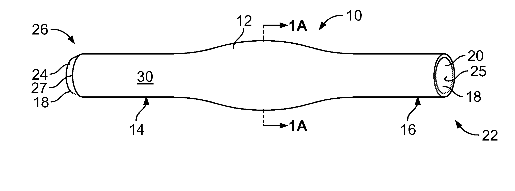
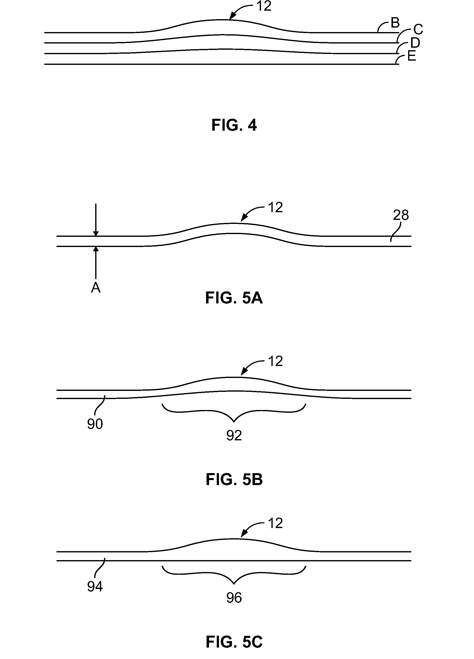
[0039] 1. Two blood vessels 90 ad 92 (FIGS. 8A and 8D) with ends of like diameter will be prepared for attachment using known surgical techniques. [0040] 2. A stent 10 will be chosen with nipples 14 and 16 having an outer diameter generally corresponding to the lumens of blood vessels 90 and 92. In an alternative embodiment, the nipples will have an outer diameter slightly greater than the native vessel diameter to produce dilation at the vessel ends. [0041] 3. The first nipple 14 of the stent will be placed within lumen 91 of the first vessel 90 (FIG. 8B) and drawn up onto the stent to approximately the midpoint of enlarged center portion 12, as shown in FIG. 8C. The center-expanded design of the stent thus causes the vessel to drape in expanded form over the stent, providing dilation of the vessel at the point of anastomosis, which minimizes the likelihood of thrombosis and clot formation. [0042] 4. A clamp 94 (illustrated diagrammatically) will then be deployed as shown in FIG. 8...

example 2

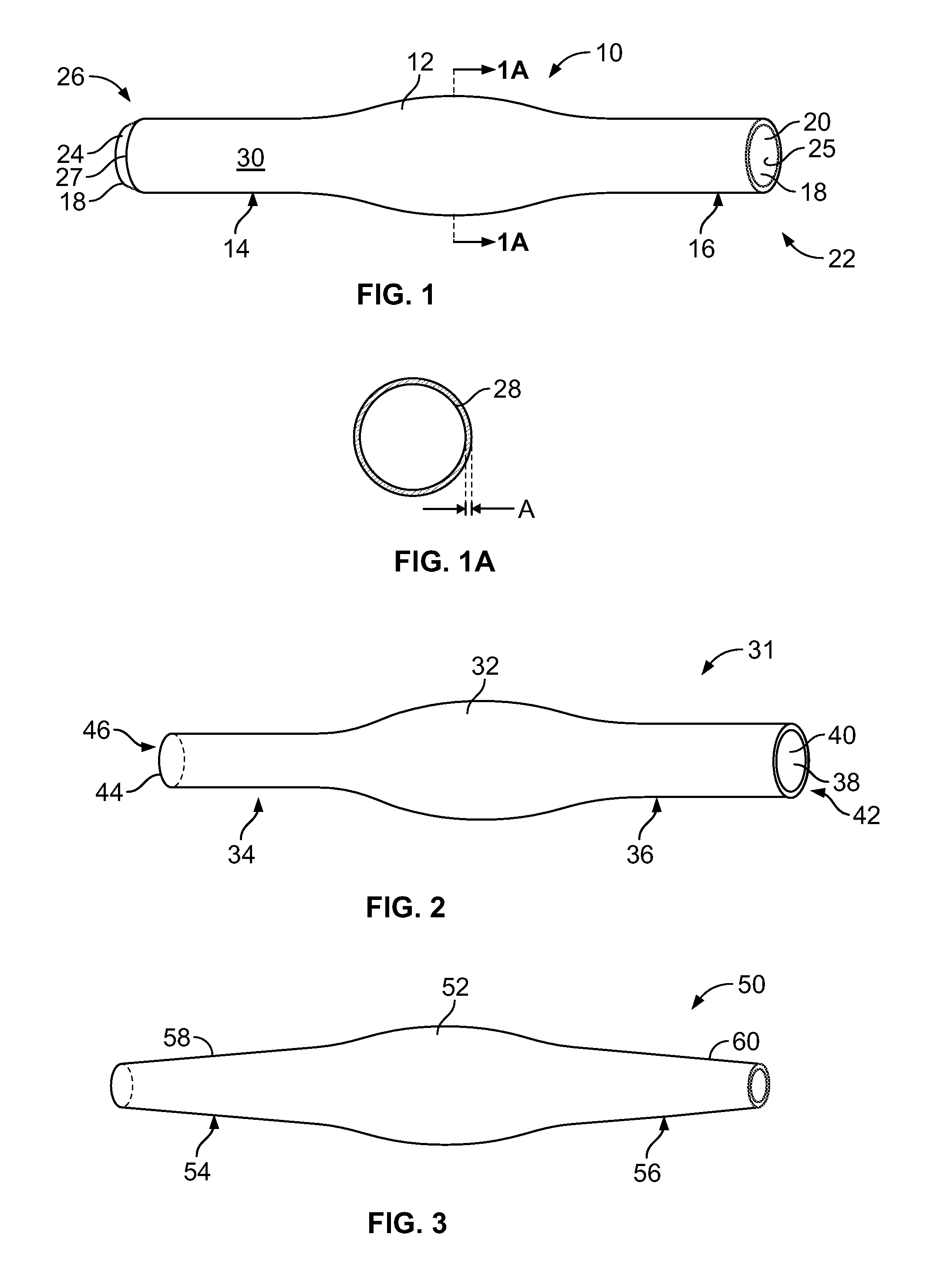
[0046] The procedure of Example 1 is followed except that vessels with different diameter lumens are joined using the stent of FIG. 2.

example 3

[0047] The procedure of Example 1 is followed except that vessels with different diameter lumens are joined using the stent of FIG. 3. Additionally, in this case the vessels are too fragile to be pulled to the midpoint of the enlarged center portion of the solid-walled stent being used and so are only pulled up onto ramping walls 58 and 60 an appropriate distance and clamped in place there.


PUM


Abstract

A method for connecting two blood vessels or other tubular organs in end-to-end fashion and a stent therefor including a central portion that may be expanded, nipples at opposite ends of the central portion and a lumen passing through the central portion and the nipples. The nipples may be of different cross-sectional sizes or funnel-shaped to enable the stent to be used in attaching two vessels or organs of different diameters.

Description

CROSS-REFERENCE TO RELATED PATENT APPLICATIONS [0001] This patent application claims the benefit of U.S. Provisional Patent Application No. 60 / 797,946, filed May 5, 2006.FIELD OF THE INVENTION [0002] The present invention relates generally to devices for connecting the ends of interrupted blood vessels, urethras or other tubular organs and, more particularly, to a stent that is secured in place within adjacent ends of two interrupted blood vessels, urethras or other tubular organs to establish flow therethrough. BACKGROUND OF THE INVENTION [0003] Vascular and microvascular surgery entails the connection of the ends of various sizes and types of interrupted blood vessels. In all cases, it is essential to obtain a secure and leak-free connection between the blood vessel ends. [0004] Currently, both vascular and microvascular surgery utilize extremely technically-demanding processes of hand sewing vessel ends to suture them together. Often, in order to insure successful outcomes, this ...

Claims


Application Information

Patent Timeline
Patent Type & Authority Applications(United States)
IPC IPC(8): A61F2/06A61F2/82
CPCA61B17/11A61F2/82A61B2017/1107A61B17/1114
Inventor KIM, JOHN Y. S.KAGANOVSKY, ARTURHENRY, MICHAEL
Owner EIDOSMED LLC
Why Eureka
Try Eureka