Multi-Pitch Screw, And Manufacturing Method And Manufacturing Apparatus Of Multi-Pitch Screw

a manufacturing method and screw technology, applied in the direction of screw, threaded fastener, manufacturing tools, etc., can solve the problems of no perfect solution, and achieve the effects of easy rolling and efficient operation, high processing precision, and difficult manufacturing

Inactive Publication Date: 2008-01-17
NAGOYA INDUSTRIAL SCIENCE RESEARCH INST
View PDF1 Cites 7 Cited by
  • Summary
  • Abstract
  • Description
  • Claims
  • Application Information

AI Technical Summary

Benefits of technology

[0031] In the invention as set forth in claim 1, a trace of a general spiral screw formed by equal pitch protrusions of an existing rotating die, and the trace of the stair step screw formed by stair step protrusions for manufacturing the screw of uneven lead angles are overlapped, and multi-pitch screw threads can be rolled easily and efficiently. Theoretically, it is possible to apply all rotating dies as rotating dies for manufacturing threads of uneven lead angles, but even though precisely processed, there is a processing error between mutual rotating dies for manufacturing the screw of uneven lead angles, the stair step screw threads rolled by stair step protrusions of one rotating die for manufacturing the screw of uneven lead angles may be flattened out by the stair step protrusions of other rotating die for manufacturing the screw of uneven lead angles, and it is practically impossible. By contrast, according to the invention of claim 1, since screw threads are not flattened out by the stair step protrusions of plural rotating dies for manufacture of screw of uneven lead angles, and without using rotating dies for manufacture of screw of uneven lead angles of very high processing precision, multi-pitch screws can be manufactured appropriately by one rotating die for manufacture of screw of uneven lead angles. Further, the rotating dies for manufacture of screw of uneven lead angles are very difficult to manufacture and expensive, but only one rotating die can be used in claim 1, and the multi-pitch screws can be manufactured economically.
[0032] In the invention of claim 1, as the rotating die for manufacturing the screw of uneven lead angles, when the one forming annular protrusions on the outer circumference is used, only part of protrusions is used in rolling, and other protrusions are used for feeding of rolled threads, and the rotating die for manufacturing the screw of uneven lead angles is preferred to be partly manufactured in a step-like uneven pitch, and the remaining protrusions are preferred to be manufactured in even pitch. This is because the manufacturing cost is increased when all protrusions are manufactured in stair steps, and it is also effective to prevent flattening of multi-pitch threads formed by part of protrusions by the feeding portion (remaining protrusions).
[0033] On the other hand, when using the one forming protrusions linked spirally on the outer circumference as the rotating die for manufacturing the screw of uneven lead angles, the protrusions can be manufactured in stair steps in the overall length.
[0034] In the invention as set forth in claim 2, the trace of the general spiral screw formed by equal pitch protrusions of the existing rotating die, and the trace of the stair step screw formed by stair step protrusions of the rotating die for manufacturing the screw of uneven lead angles are overlapped, and multi-pitch screw threads can be rolled easily and efficiently. Since only one rotating die for manufacturing the screw of uneven lead angles is used, screw threads are not flattened out by stair step protrusions of the plurality of rotating dies for manufacture of screw of uneven lead angles. Further, the rotating dies for manufacturing the screw of uneven lead angles are very difficult to manufacture and expensive, but only one rotating die can be used and stair case protrusions are provided only in part in claim 2, and multi-pitch screws can be manufactured at low cost. The rotating die for manufacturing the screw of uneven lead angles is manufactured in stair step protrusions only in part, and the remaining protrusions are in even pitch, and it is effective to prevent flattening of multi-pitch threads formed by the part of stair step protrusions by the feeding portion (the remaining protrusions).
[0035] Further in the invention of claim 2, even pitch protrusions of the rotating die for manufacturing the screw of even lead angles are higher than stair step protrusions of the rotating die for manufacturing the screw of uneven lead angles, and narrower in width. Accordingly, the even pitch protrusions of the rotating die for manufacturing the screw of even lead angles are forming the lowest portion of the multi-pitch screw during the process, and the multi-pitch screw can be processed stably and continuously.
[0036] In the invention as set forth in claim 3, since the sectional area of even pitch protrusions and stair step protrusions is set nearly the same, and the load applied to the rotating die for manufacturing the screw of even lead angles and the rotating die for manufacturing the screw of uneven lead angles is uniform, and threads of the multi-pitch screw can be rolled stably.

Problems solved by technology

Various countermeasures have been proposed against loosening of screw for tightening, but nothing has been perfect.

Method used


Image

  • Multi-Pitch Screw, And Manufacturing Method And Manufacturing Apparatus Of Multi-Pitch Screw
  • Multi-Pitch Screw, And Manufacturing Method And Manufacturing Apparatus Of Multi-Pitch Screw
  • Multi-Pitch Screw, And Manufacturing Method And Manufacturing Apparatus Of Multi-Pitch Screw

Examples


first embodiment

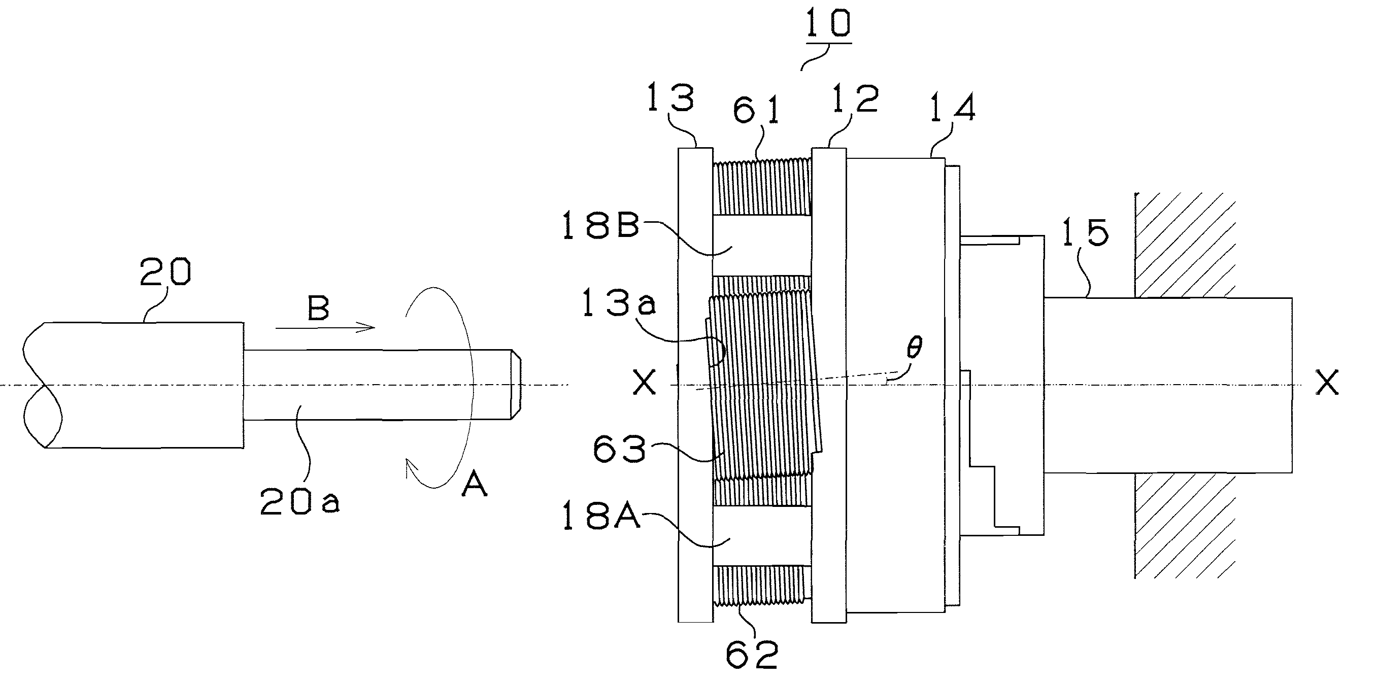
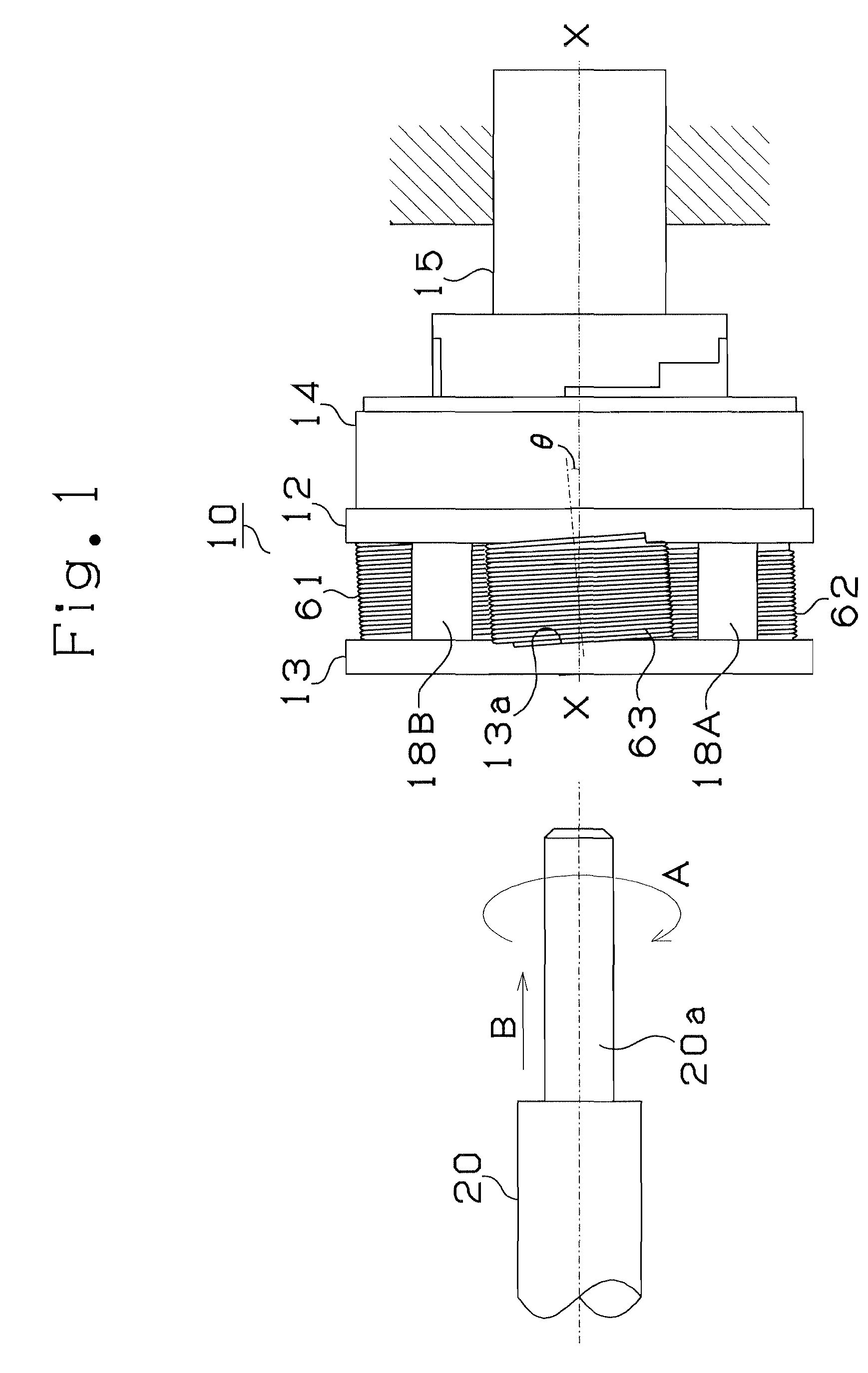
[0049] Referring first to FIG. 1 to FIG. 3, an outline of manufacturing method and manufacturing apparatus in a first embodiment of the invention is explained. A rolling head 10 is a conventional one using three rotating dies, and of the three rotating dies 61, 62, 63, the rotating dies 61 and 62 are for manufacturing the screw of even pitches conforming to the conventional structure, and the rotating die 63 has an own structure of the first embodiment. The rotating dies 61, 62 are for manufacturing the screw of even lead angles, and the rotating die 63 is for manufacturing the screw of uneven lead angles.

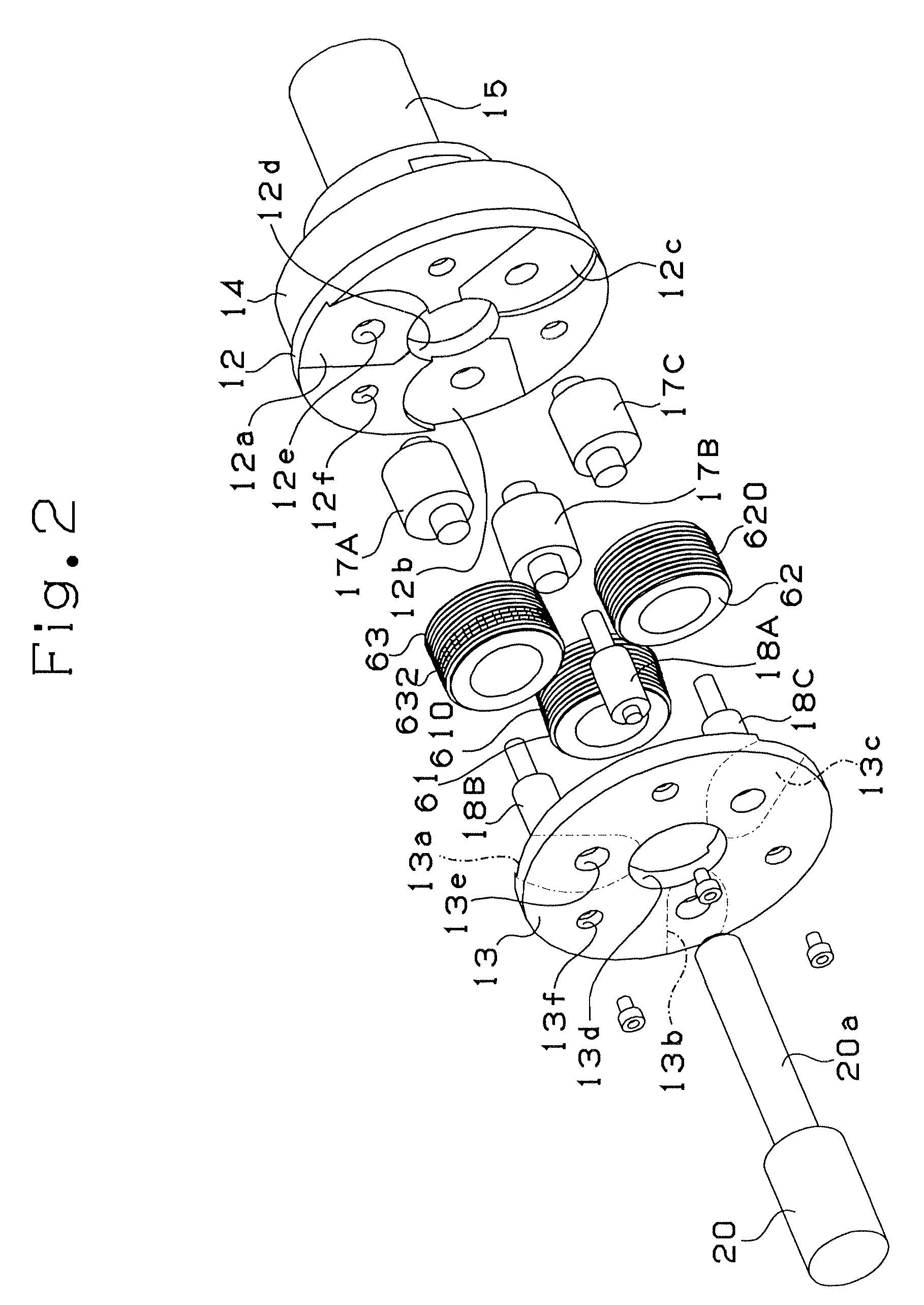
[0050] As shown in FIG. 2, the rolling head 10 has a circular base plate 12 having a through-hole 12d in the center, and a circular fixed plate 13 having a through-hole 13d in the center, and at one side of the base plate 12, a control mechanism 14 incorporating a clutch and a fixed shaft 15 are assembled. Between the other side of the base plate 12 and the fixed plate 13, three c...

second embodiment

[0077] A second embodiment is described by referring to FIG. 9 and FIG. 10. FIG. 9 shows a rolling head 110 used in the second embodiment, FIG. 10A shows a rotating die 161 (162) for manufacturing the screw of even lead angles used in the rolling head 110, and FIG. 10B shows a rotating die 163 for manufacturing the screw of uneven lead angles used in the rolling head 110. In the first embodiment, the rotating dies 61, 62, 63 have annular protrusions 610, 620, 630, 632 on the outer circumference. In the second embodiment, by contrast, the rotating die 161 for manufacturing the screw of even lead angles and the rotating die 163 for manufacturing the screw of uneven lead angles have spirally linked protrusions 1610 and 1630 on the outer circumference. Further, in the first embodiment, uneven lead angle protrusions 631, 632, 633 are formed only in part of the rotating die 63 for manufacturing the screw of uneven lead angles, but in the second embodiment, uneven lead angle protrusions 16...


PUM

PropertyMeasurementUnit
lead anglesaaaaaaaaaa
circumferenceaaaaaaaaaa
widthaaaaaaaaaa

Abstract

The invention presents a method of manufacturing a multi-pitch screw having desired threads and pitches by rolling. A trace of general (even lead angle) spiral screw is formed by even pitch protrusions 610 and 620 of an existing rotating dies 61 and 62, and it is combined with a trace of stair step screw formed by stair step protrusions 632 of a rotating die 63 of uneven lead angle, and multi-pitch screw threads are formed efficiently. Herein, only one rotating die 61 of uneven lead angle is used, and screw threads are not flattened out by stair step protrusions of the plurality of rotating dies of uneven lead angles.

Description

TECHNICAL FIELD [0001] The invention relates to a multi-pitch screw having a plurality of leads (a multi-pitch screw forming screw threads spirally, with a moderate section of a lead angle and a steep section of a lead angle formed alternately and continuously in one revolution of a spiral form), a manufacturing method of the multi-pitch screw, and an apparatus for manufacturing the same. BACKGROUND ART [0002] Various countermeasures have been proposed against loosening of screw for tightening, but nothing has been perfect. [0003] Changing the conventional concept of a screw (a screw having a constant pitch), the inventors have studied and confirmed that the problem can be solved by a new concept of a screw, that is, a screw having a plurality of leads, or a multi-pitch screw having lead portions differing in a pitch formed continuously (see non-patent document 1). [0004] The inventors have also proposed a structure and combination of a bolt and a nut of a multi-pitch screw having a...

Claims


Application Information

Patent Timeline
Patent Type & Authority Applications(United States)
IPC IPC(8): B23P13/04
CPCB21H3/04B21H3/046Y10T29/5109Y10T29/49996F16B33/02
Inventor FUJII, HIROSHISASE, NAOKIKATAYAMA, KENICHIMORIGUCHI, YOSHINORI
Owner NAGOYA INDUSTRIAL SCIENCE RESEARCH INST
Why Eureka
Try Eureka