Screw prestressing device and method

Inactive Publication Date: 2008-01-17
AIRBUS DEFENCE & SPACE
View PDF7 Cites 5 Cited by
  • Summary
  • Abstract
  • Description
  • Claims
  • Application Information

AI Technical Summary

Benefits of technology

[0014] One advantage of the screw prestressing device according to the invention is that this screw prestressing device is suitable for cleanroom applications without special complex additional measures being necessary.
[0015] Another advantage of the screw prestressing device according to the invention is that this screw prestressing device is suitable for applications in connection with highly sensitive optical elements; i.e., these highly sensitive optical elements are not destroyed by the use of the screw prestressing unit.
[0016] Another advantage of the screw prestressing device according to the invention is that this screw prestressing device is able to tighten screws utilizing the maximum permissible prestressing, without the influence of torque, and while at the same time with the highest cleanness class. In particular, when used on so-called optical benches, threaded assemblies are to be tightened, if possible, without the influence of torque, while at the same time maintaining the highest cleanness class. Every friction produced (e.g., metal on metal, but also metal on ceramic) inevitably leads to abrasive wear, which in turn can also impact the optical surfaces.
[0017] Another advantage of the screw prestressing device according to the invention is that this screw prestressing device supports the possibility of monitoring threaded assemblies during the tightening process in a two-fold manner (via hydraulic pressure monitoring and via ultrasonic stretching measurement).
[0018] Another advantage of the screw prestressing device according to the invention is that this screw prestressing device is able to tighten threaded assemblies with the highest prestressing forces. Thus, for example, depending on the screw material used (e.g., titanium, steel, or inconel), the screws can be tightened to within a few percent of their permissible yield point.

Problems solved by technology

These standard threaded assemblies have the disadvantage that if the maximum prestressing forces are utilized in the screw, or stud, torques are inevitably transferred via the unavoidable thread friction.
Due to the superimposition of the stress in the screw, or stud (tensile stress plus shearing stress), the threaded assembly cannot be tightened up to the maximum permissible tensile stress.
Furthermore, in the case of delicate parts, such as, e.g., the ceramic mirrors of a spectrometer (e.g., in the NirSpec space project), the transfer of the thread torque to the flange to be tightened leads to an unacceptable and inadmissible deformation of the mirror surface.
In-house tests with conventional tightening methods have shown that torques transferred to the ceramic mirror foot have a negative impact (i.e., performance loss) on the high demands on the mirror surface.
However, these units are known only for very large threaded assemblies (from diameter M24 upwards) and all operate on the basis of oil hydraulics.
Additionally, water hydraulic screw prestressing devices are not known in the prior art.
Through the use of an oil hydraulic system, these screw prestressing devices have the disadvantage that in practice they are not suitable for cleanroom applications, such as are necessary, e.g., in applications in the field of space flight.
An oil hydraulic system can be used in a cleanroom only to a limited extent, namely with special, complex additional measures.
The known hydraulic screw prestressing units, which are known only for very large threaded assemblies, furthermore have the disadvantage that, in the case of damage, they would lead to a destruction of sensitive elements, e.g., highly sensitive optical elements, such as are used in the field of space flight.
Every friction produced (e.g., metal on metal, but also metal on ceramic) inevitably leads to abrasive wear, which in turn can impact the optical surfaces.

Method used


Image

  • Screw prestressing device and method
  • Screw prestressing device and method
  • Screw prestressing device and method

Examples


Embodiment Construction

[0049] The particulars shown herein are by way of example and for purposes of illustrative discussion of the embodiments of the present invention only and are presented in the cause of providing what is believed to be the most useful and readily understood description of the principles and conceptual aspects of the present invention. In this regard, no attempt is made to show structural details of the present invention in more detail than is necessary for the fundamental understanding of the present invention, the description taken with the drawings making apparent to those skilled in the art how the several forms of the present invention may be embodied in practice.

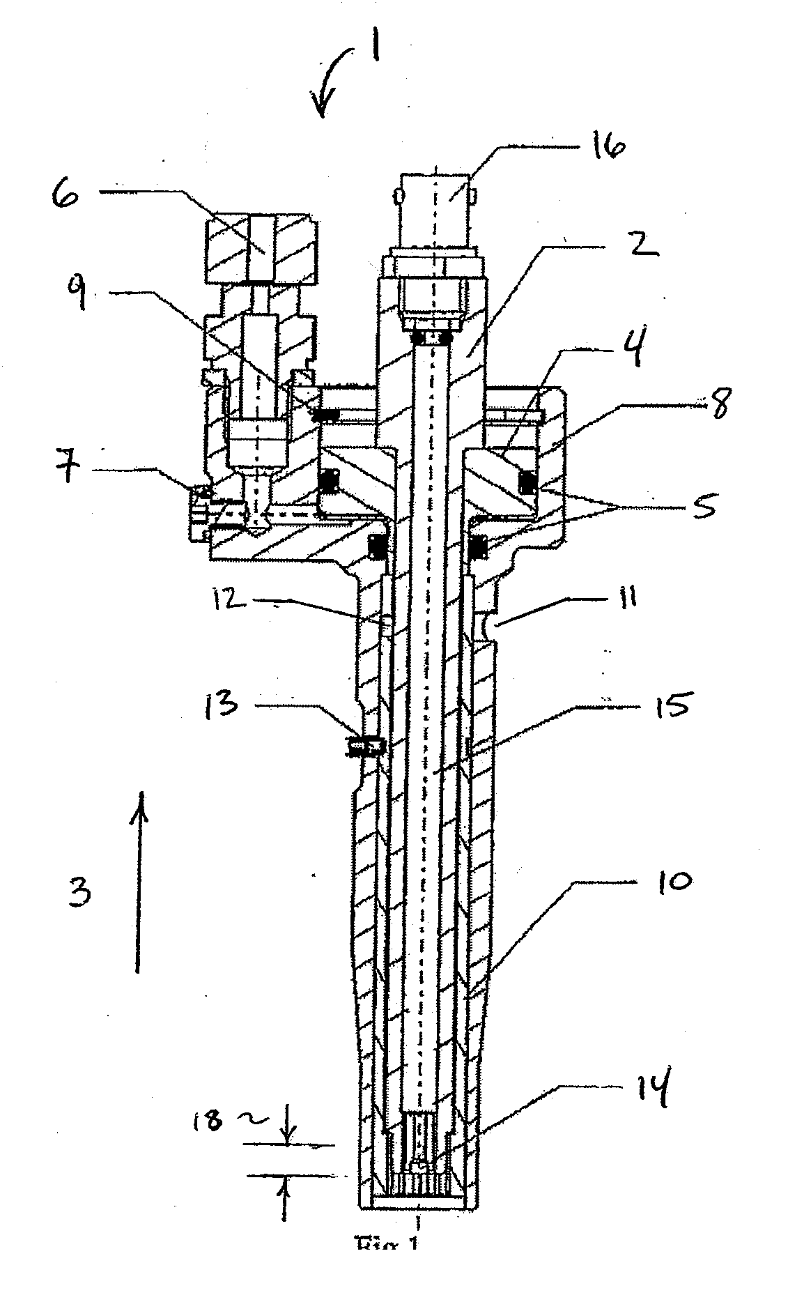
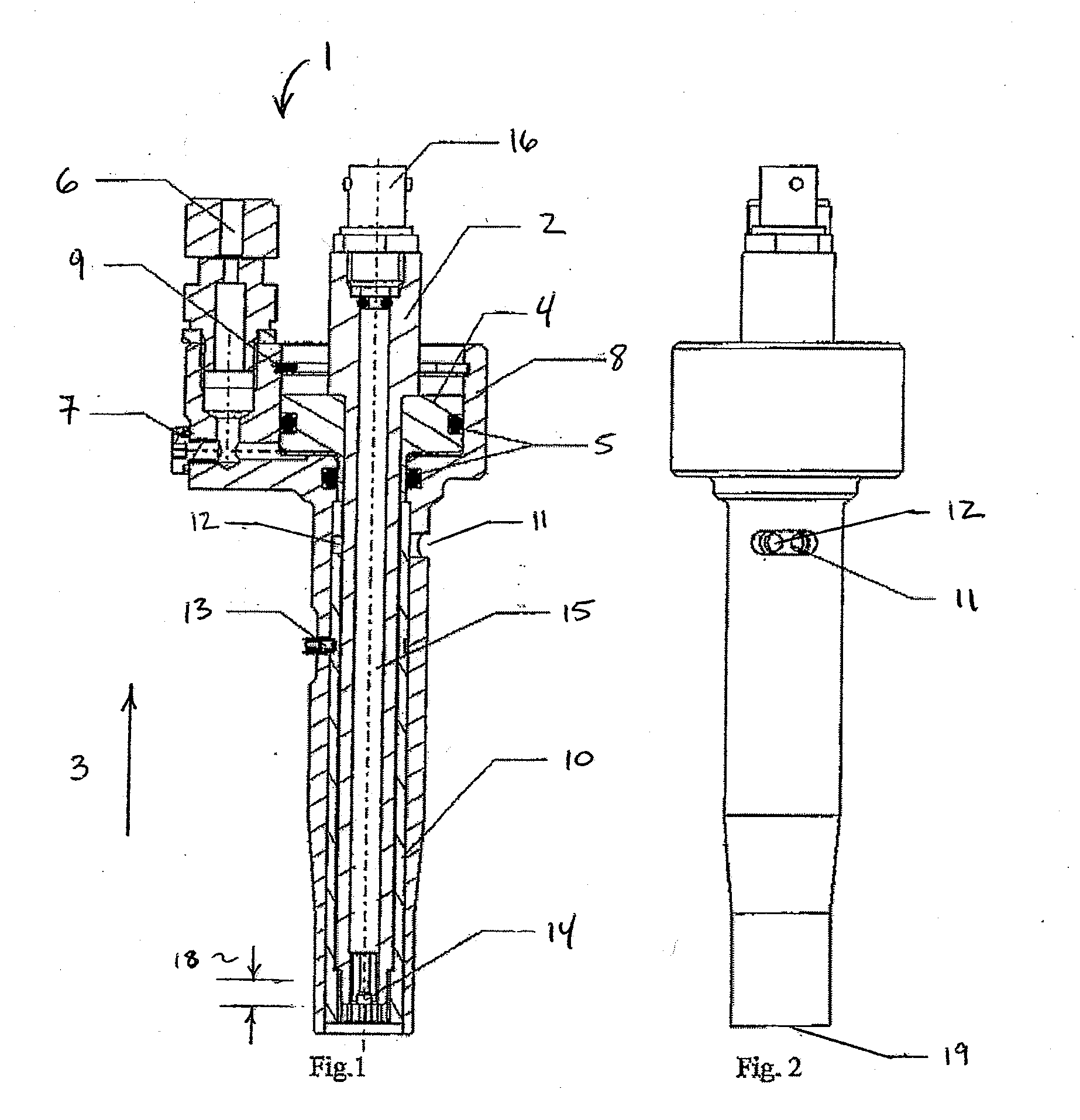
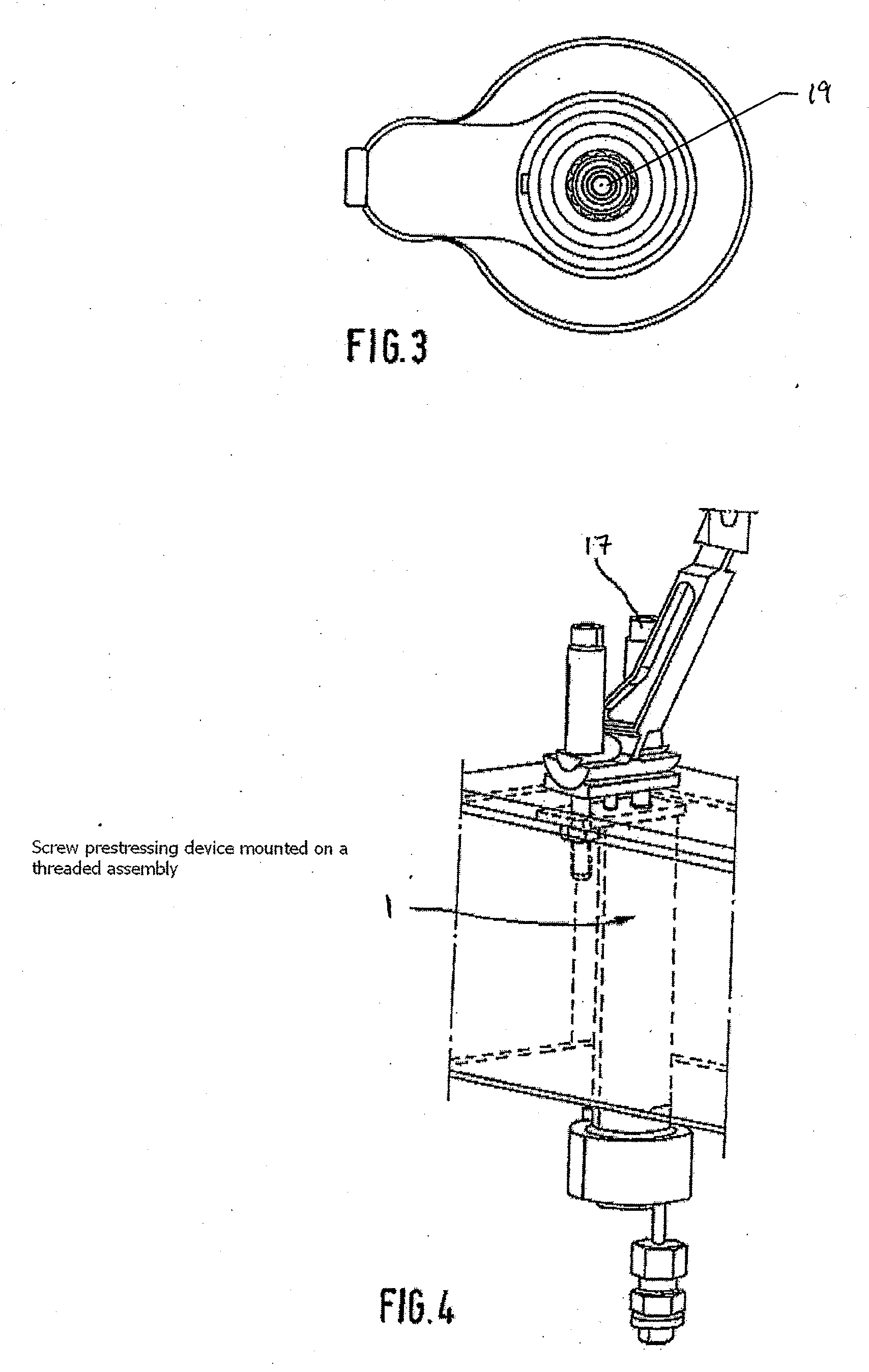
[0050] Embodiments of the screw prestressing device according to the invention are described below in connection with the drawings. The invention relates to a water hydraulic screw prestressing unit that is suitable in particular for small screw diameters (e.g., from M4 to M12 of the metric ISO standard, or equivalent s...


PUM

PropertyMeasurementUnit
Forceaaaaaaaaaa
Pressureaaaaaaaaaa
Sizeaaaaaaaaaa

Abstract

A screw prestressing device having a piston and a draw pin structured and arranged to be disconnectably coupled to an element and movable, via the piston, to apply a defined prestressing force in the element.

Description

CROSS-REFERENCE TO RELATED APPLICATIONS [0001] The present application claims priority under 35 U.S.C. § 119 of German Application No. 10 2006 033 320.9-12 filed Jul. 17, 2006, the disclosure of which is expressly incorporated by reference herein in its entirety. BACKGROUND OF THE INVENTION [0002] 1. Field of the Invention [0003] The invention relates to a water hydraulic screw prestressing device free of torque with integrated ultrasonic prestressing monitoring. [0004] 2. Discussion of Background Information [0005] Threaded assemblies provide detachable connections of components. The important factor for these connections is the spring action of the screw and screwed parts (flange). Tightening a screw with a prestressing force causes a stretching of the screw and a compression of the flange. The resulting friction produces a connection of the two parts in the radial direction, where the prestressing force itself blocks the axial degree of freedom of the parts involved. [0006] The m...

Claims


Application Information

Patent Timeline
IPC IPC(8): B25B23/151
CPCB23P19/067Y10T29/49863B25B29/02
Inventor WEIMER, PETER
Owner AIRBUS DEFENCE & SPACE
Why Eureka
Try Eureka