

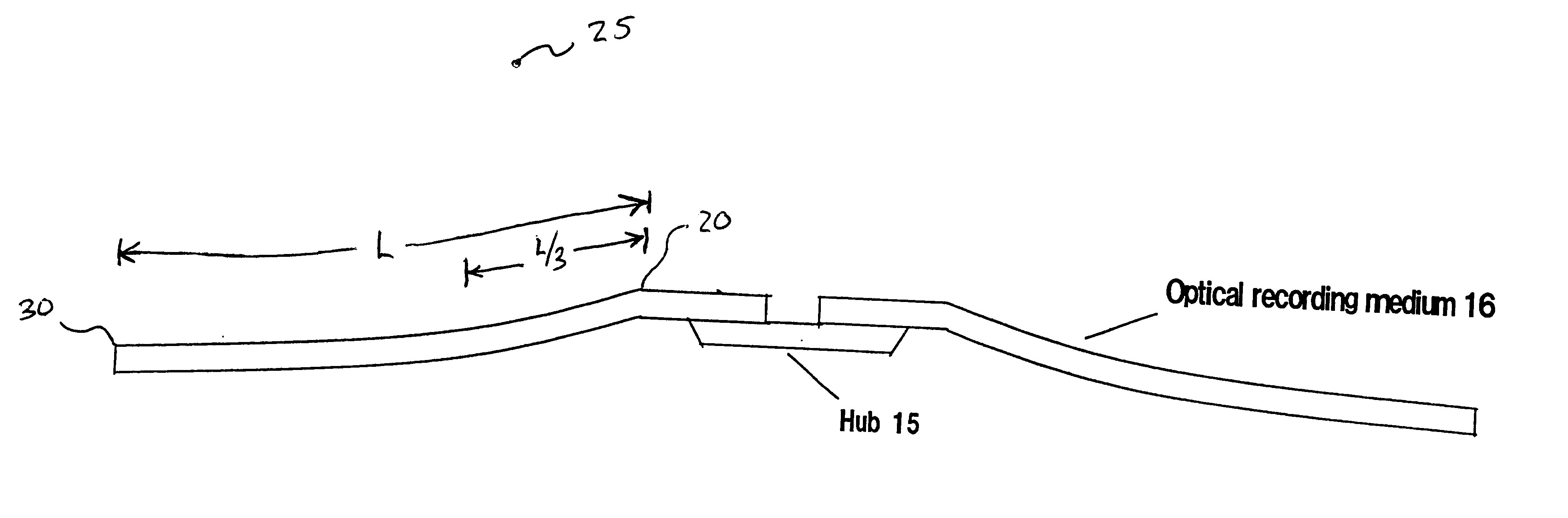
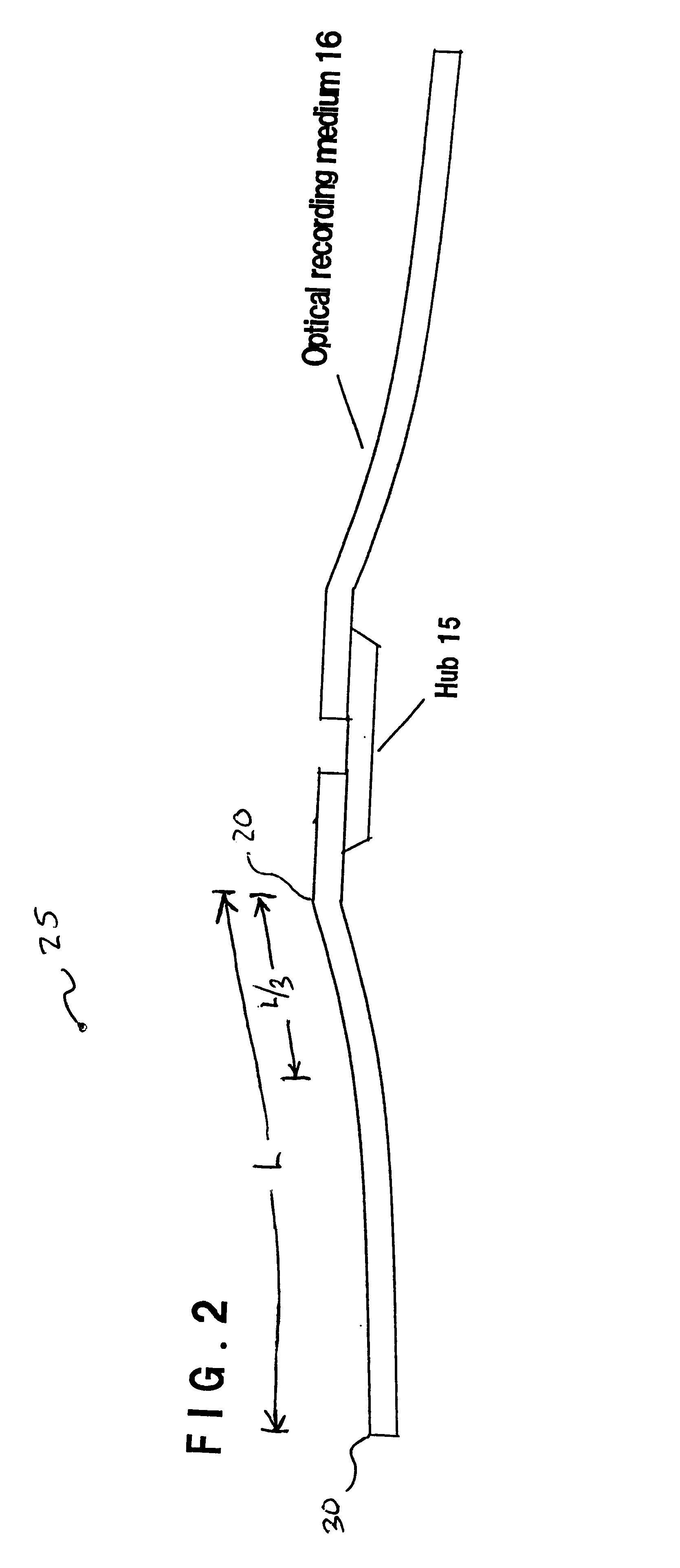
Optical recording medium having in a static mode, a flexible region extending to 1/3 of the recording area
- Summary
- Abstract
- Description
- Claims
- Application Information
AI Technical Summary
Benefits of technology
Problems solved by technology
Method used
Image

Examples
example 1
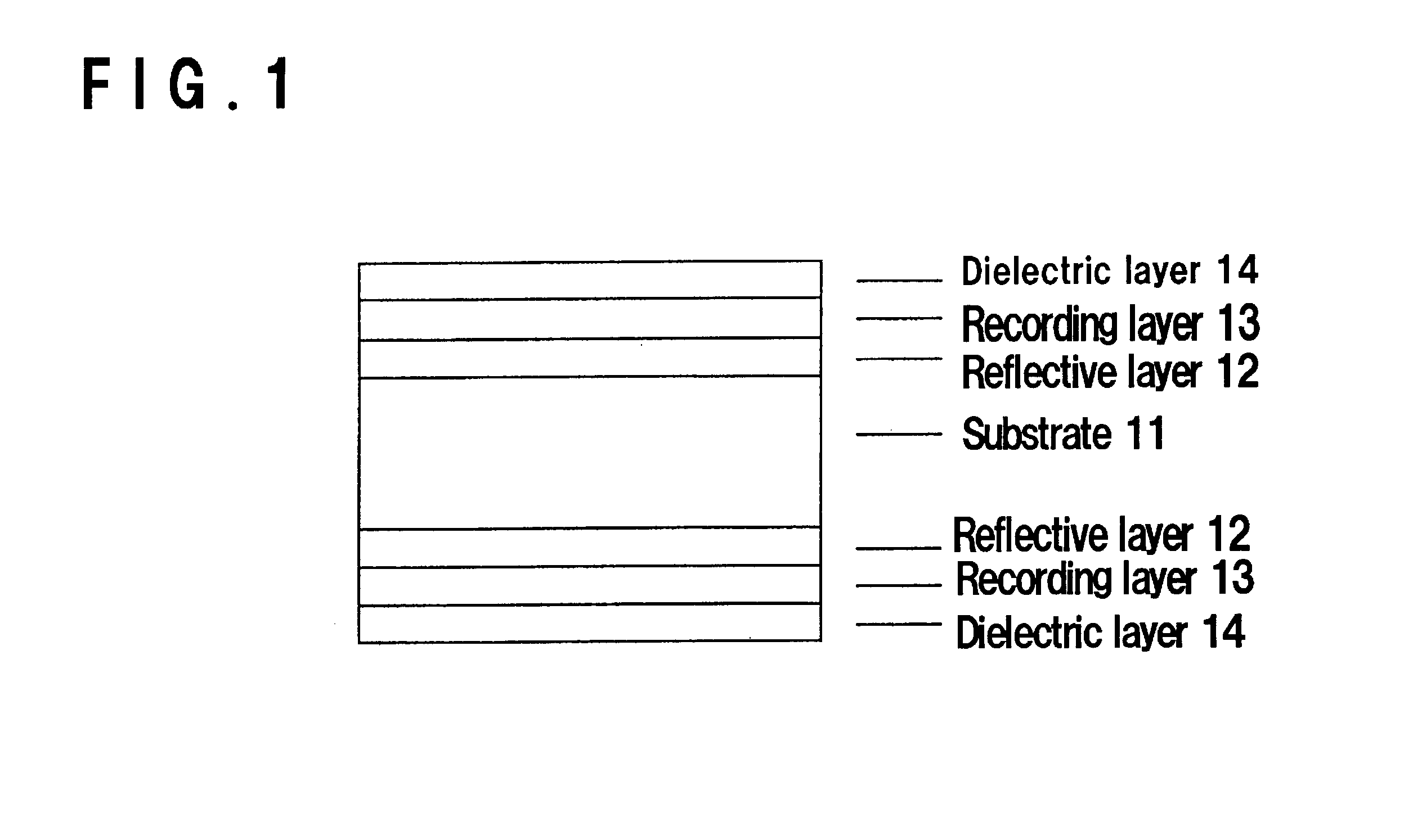
[0071]A circular substrate made of polycarbonate having a diameter of 130 mm and a thickness of 2 mm in which spiral land / groove portions having a track pitch of 0.43 μm, a header portion and an optical recording / reproducing area (L) formed in a range of radius of 20˜60 mm were formed in both front and rear surfaces, was prepared by injection-molding at a die-clamping pressure of 120 kg / cm2 at the maximum. As metallic dies used for the shaping, metallic dies having a structure comprising a moving side metallic die and a stationary side metallic die were used wherein the temperature of the mirror plate of the moving side metallic die was adjusted to 112° C. and the temperature of the mirror plate of the stationary side metallic die was adjusted to 110° C.
[0072]By using the substrate, layers were formed on both surfaces of the substrate by a sputtering method in a manner as described below.
[0073]First, on the substrate, a Al-3 wt % Cr alloy layer having a layer thickness of 50 nm was ...
example 2
[0077]A magneto-optical recording medium capable of recording / reproducing in both surfaces was prepared by the same method as in Example 1 except that a pressure difference of air for blowing at the time of removing the substrate from the metallic dies in obtaining the substrate by injection-molding was provided between the stationary side metallic die and the moving side metallic die, and the pressure at the stationary side was 0.5 kg / cm2 higher than that at the moving side. Then, the radius of curvature of the substrate was measured.
example 3
[0090]A circular substrate made of polycarbonate having a diameter of 130 mm and a thickness of 2 mm in which spiral land / groove portions having a track pitch of 0.43 μm and a header portion were formed in both front and rear surfaces, was prepared by an injection-molding method. The metallic dies used for shaping were of a structure that the metallic dies comprised a pair of a moving portion and a stationary portion wherein a plastified resin was injected from a side of the stationary portion, and floating punch and protrusion pin were moved from a side of the moving portion to remove the substrate. The substrate was prepared by operating the floating punch and the protrusion pin after 5 seconds of opening the moving metallic die after the completion of the injection. The temperature of each of the stationary portion and the moving portion of the metallic dies was 110° C.
[0091]By using the substrate, layers were formed on both surfaces of the substrate by a sputtering method as des...
PUM
 Abstract
Description
Claims
Application Information