Electronic grade glass substrate and making method
a technology of electronic grade glass and substrate, applied in the direction of manufacturing tools, lapping machines, instruments, etc., can solve the problems of cracking of the corner between the side and bottom surfaces of the recess, and the cracking of the corner. , to achieve the effect of high strength and cleanness, increased strength of the bottom wall, and high accuracy
- Summary
- Abstract
- Description
- Claims
- Application Information
AI Technical Summary
Benefits of technology
Problems solved by technology
Method used
Image
Examples
example 1
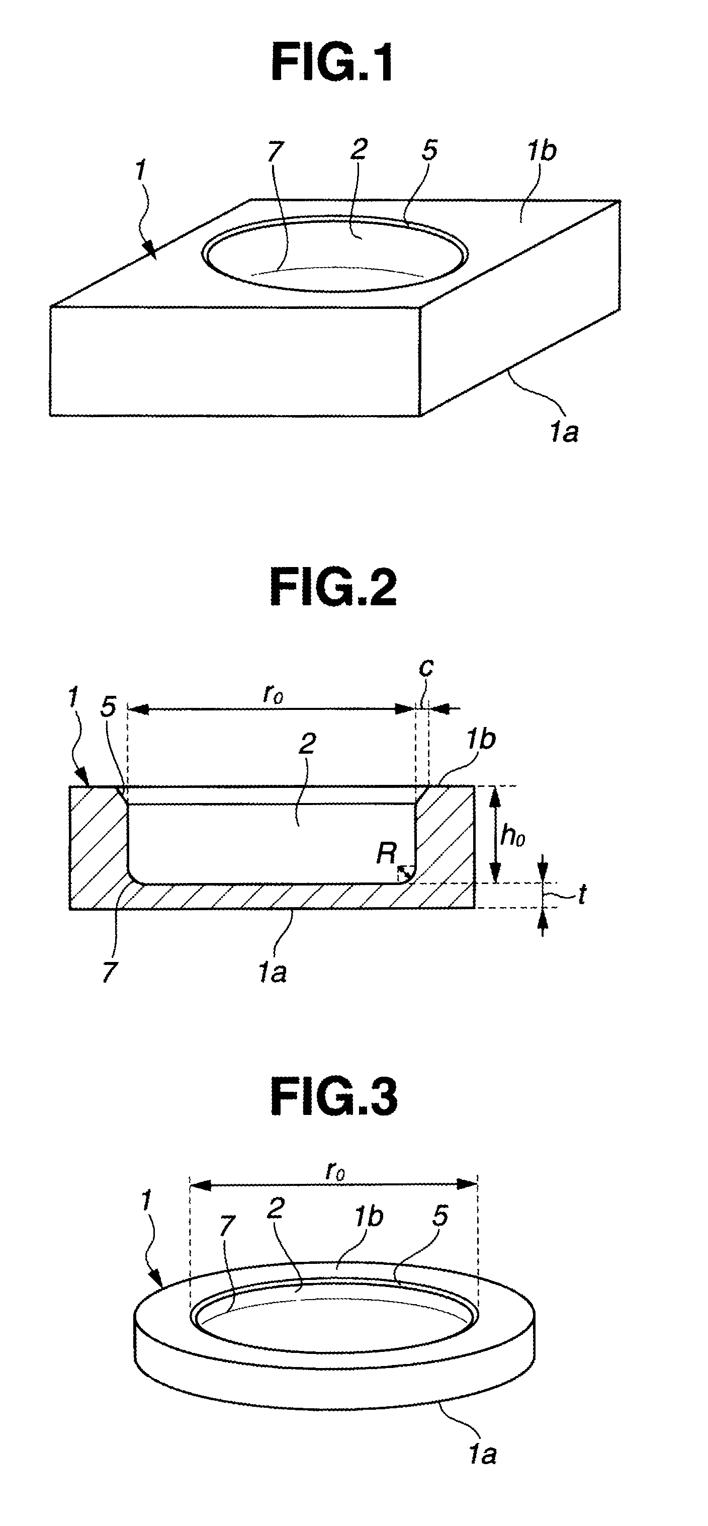
[0072]A synthetic quartz glass substrate A dimensioned 100 mm×100 mm×6.35 mm (thick) having front, back and end surfaces polished to mirror finish was prepared as a starting substrate. Using a machining center and a diamond abrasive wheel, the starting substrate was machined at the center of its back surface to form a circular recess with a depth of 5.32 mm and a diameter of 69.98 mm, having a first chamfer with a width of 0.3 mm between the recess side surface and the substrate back surface.
[0073]Next, the machined substrate was fixedly mounted on a platform. A wool felt buff having a diameter of 50 mm and a height of 30 mm adapted to rotate at 1,000 rpm was forced in contact with the bottom surface of the recess under 3,500 Pa and the side surface under 2,000 Pa. The substrate-holding platform was rotated at 10 rpm, whereby the surfaces were polished for 60 minutes to mirror finish. The recess (or counterbore) in the glass substrate as polished had a depth of 5.35 mm with a bottom...
example 2
[0080]A synthetic quartz glass substrate A dimensioned 100 mm×100 mm×6.35 mm (thick) having front, back and end surfaces polished to mirror finish was prepared as a starting substrate. Using a machining center and a diamond abrasive wheel, the starting substrate was machined at the center of its back surface to form a circular recess with a depth of 5.32 mm and a diameter of 69.98 mm, having a curvilinear second chamfer with a radius of curvature of 1.5 mm between the recess side and bottom surfaces and a first chamfer with a width of 0.3 mm between the recess side surface and the substrate back surface.
[0081]Next, the machined substrate was fixedly mounted on a platform. A wool felt buff having a diameter of 50 mm and a height of 30 mm adapted to rotate at 1,000 rpm was forced in contact with the bottom surface of the recess under 3,500 Pa and the side surface under 2,000 Pa. The substrate-holding platform was rotated at 10 rpm, whereby the surfaces were polished for 60 minutes to ...
example 3
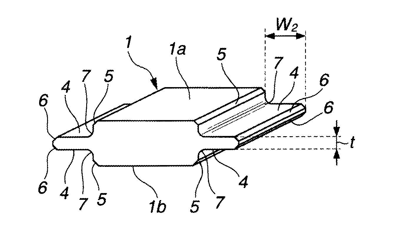
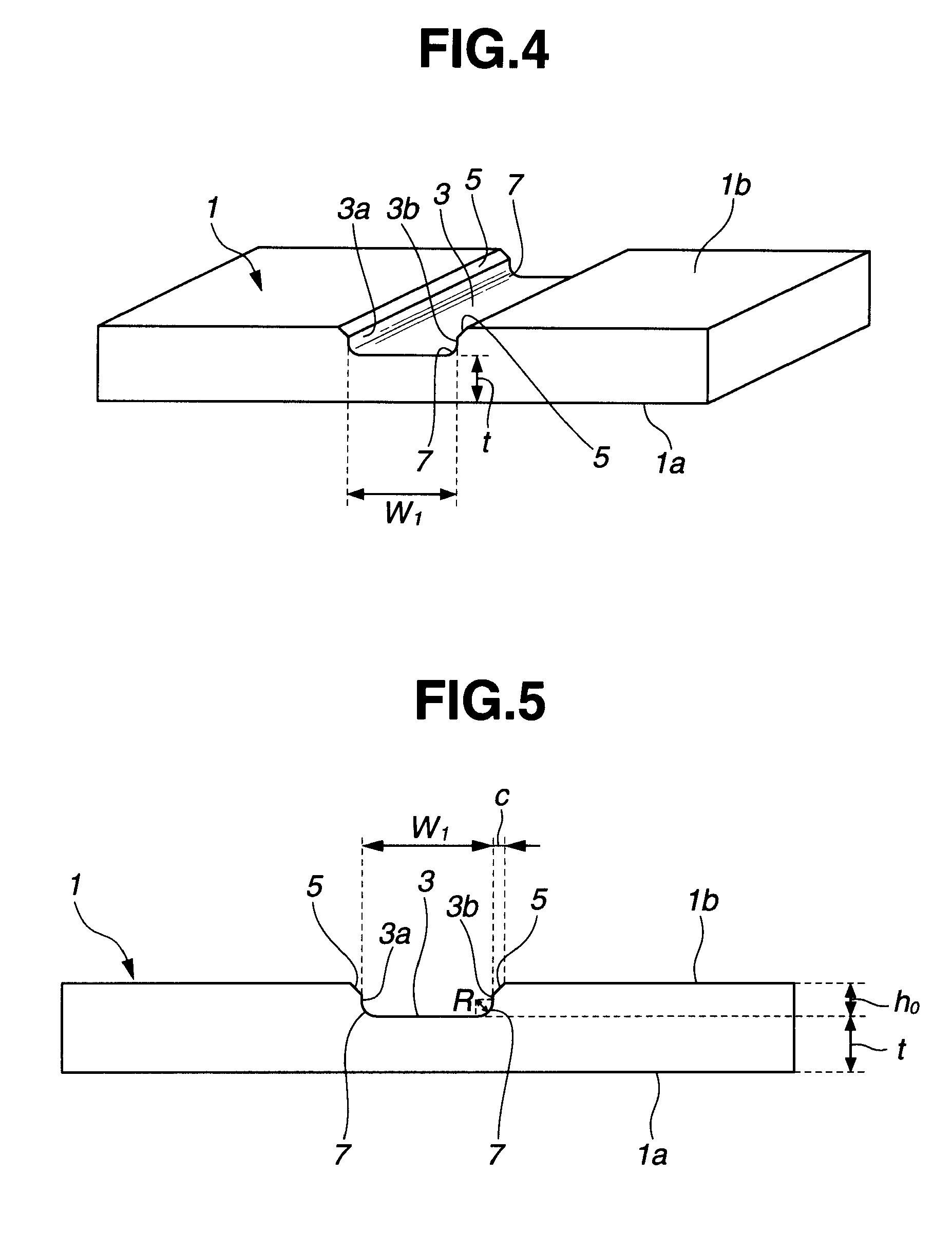
[0091]A synthetic quartz glass substrate B dimensioned 152 mm×152 mm×6.35 mm (thick) having front, back and end surfaces polished to mirror finish was prepared as a starting substrate. Using a machining center and a diamond abrasive wheel, the starting substrate was machined at the center of its back surface to form a channel having a depth of 4.98 mm, a width of 29.9 mm, and a length of 152 mm, extending parallel to the end surface, and having a curvilinear second chamfer with a radius of curvature of 0.9 mm between the channel side and bottom surfaces and a first chamfer with a width of 0.3 mm between the channel side surface and the back surface.
[0092]Next, the machined substrate was fixedly mounted on a platform. A wool felt buff having a diameter of 30 mm and a height of 30 mm adapted to rotate at 1,000 rpm was forced in contact with the bottom surface of the channel under 2,000 Pa and one side wall under 2,000 Pa. The substrate-holding platform was moved back and forth at 50 m...
PUM
| Property | Measurement | Unit |
|---|---|---|
| Ra | aaaaa | aaaaa |
| flatness | aaaaa | aaaaa |
| Young's modulus | aaaaa | aaaaa |
Abstract
Description
Claims
Application Information
 - R&D
- Intellectual Property
- Life Sciences
- Materials
- Tech Scout
- Unparalleled Data Quality
- Higher Quality Content
- 60% Fewer Hallucinations
Browse by: Latest US Patents, China's latest patents, Technical Efficacy Thesaurus, Application Domain, Technology Topic, Popular Technical Reports.
© 2025 PatSnap. All rights reserved.Legal|Privacy policy|Modern Slavery Act Transparency Statement|Sitemap|About US| Contact US: help@patsnap.com


