Tapping assembly

a technology of transmission lines and assembly parts, which is applied in the direction of pipe elements, mechanical equipment, transportation and packaging, etc., can solve the problems of compromising the structural integrity of the transmission line, and achieve the effect of reducing the chance and minimizing the structure that rises above the transmission lin

a technology of transmission lines and assembly parts, which is applied in the direction of pipe elements, mechanical equipment, transportation and packaging, etc., can solve the problems of compromising the structural integrity of the transmission line, and achieve the effect of reducing the chance and minimizing the structure that rises above the transmission lin

US20080011358A1Inactive Publication Date: 2008-01-17BRANDT MARK U +1

Image

  • Tapping assembly
  • Tapping assembly
  • Tapping assembly

Examples


Embodiment Construction

[0016]Referring now in more detail to the drawing figures, and initially to FIG. 1, a tapping assembly of the present invention designated by reference numeral 10 is shown in use on a transmission line 100, such as a natural gas or water conduit main. The tapping assembly 10 provides a junction between the transmission line 100 and a service or branch line (not shown) connected with a branch outlet 12 of the tapping assembly 10, as can be seen with further clarity in FIG. 2. The tapping assembly generally includes a unitary saddle fitting 14 and a coupling device 16 for coupling or initially securing the saddle fitting 14 onto a section of a structural wall 102 of the transmission line 100 prior to engaging in a tapping sequence on the transmission line 100.

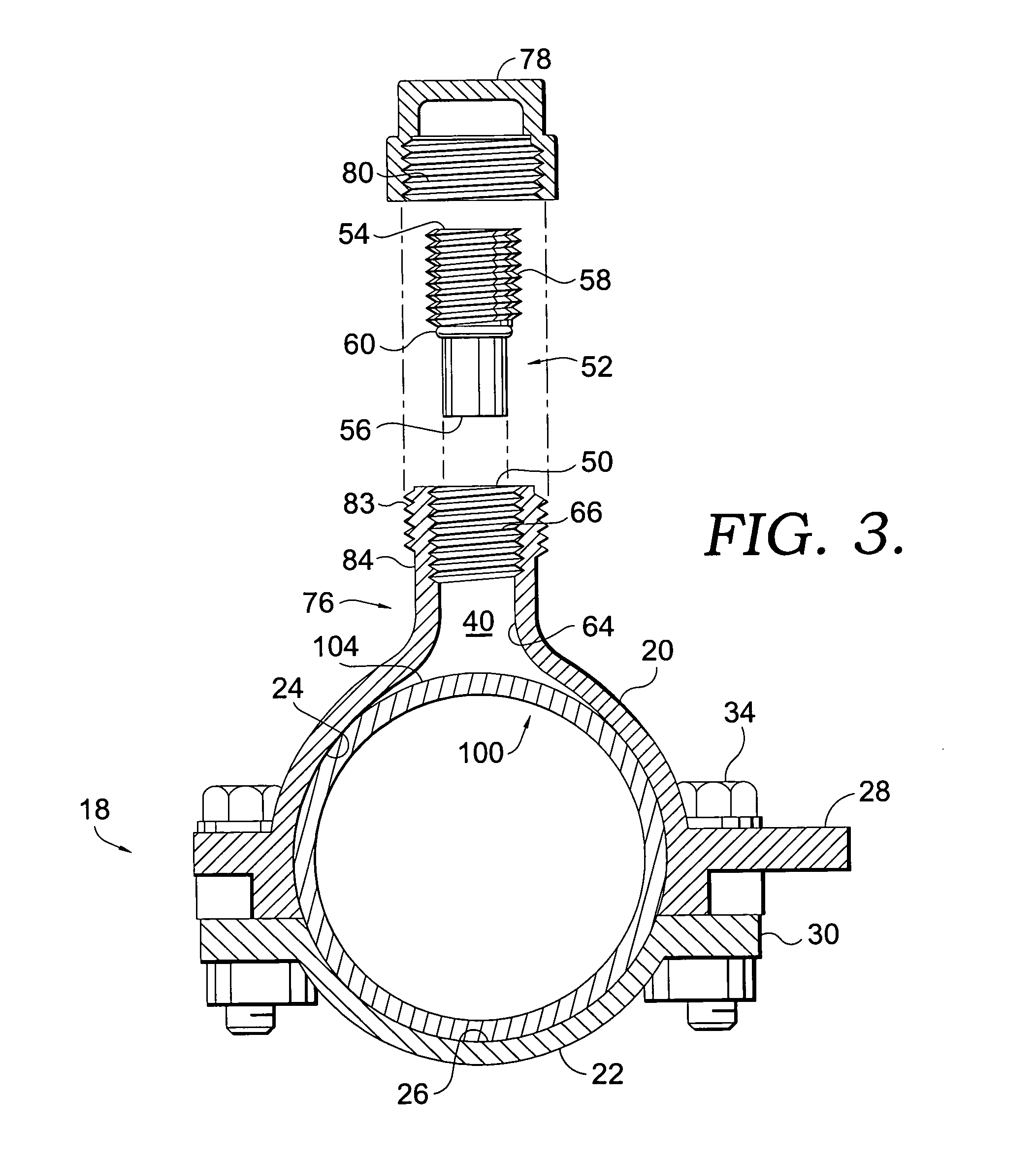
[0017]For instance, as illustrated in FIG. 1, and with additional reference to FIG. 3, one embodiment of the tapping assembly 10 includes an adjustable split collar 18 serving as the coupling device 16. The collar 18 is formed by...


PUM

PropertyMeasurementUnit
diameteraaaaaaaaaa
diameteraaaaaaaaaa
diameteraaaaaaaaaa

Abstract

A tapping assembly implements a unitary saddle fitting design to enable the formation of a branch connection with a polymeric flowable material transmission line. The tapping assembly includes a unitary saddle fitting and a set of cutting elements operative to create openings in a structural wall of the transmission line and thereby form a fluid communication pathway from the transmission line through the saddle fitting and onto a service line connected with the tapping assembly.

Description

CROSS-REFERENCE TO RELATED APPLICATIONS[0001]Not applicable.STATEMENT REGARDING FEDERALLY SPONSORED RESEARCH OR DEVELOPMENT[0002]Not applicable.BACKGROUND OF THE INVENTION[0003]With the modernization of fluid and gas transmission networks, conduit mains for delivering to homes and businesses are increasingly more likely to be fabricated from polymeric materials, such as polyvinyl chloride (PVC) and other plastic-type materials. These utility mains are typically routed adjacent to or beneath streets in horizontally oriented trenches to convey pressurized natural gas or water from a main supply source to various locations where service line conduits tap into the main and draw gas or water therefrom. As a rule of thumb for supplying natural gas, service lines typically range from one-half inch to two inches in diameter depending on the level or service needed for the particular line, although service lines can also be much larger. Each service line may serve a single building structure...

Claims


Application Information

Patent Timeline
17 Jan 2008
Publication
US20080011358A1
IPC
F16L55/18
CPC
F16L47/345; Y10T137/6123
Inventors
BRANDT, MARK U.; EGGERS, TIMOTHY L.