
Inductive heating element

a heating element and inductive technology, applied in the field of inductive heating elements, can solve the problems of ineffective heating of gas through holes, difficulty in increasing both inductive heating efficiency and heat exchange effectiveness concurrently, etc., to achieve high heat exchange efficiency, increase heat exchange effectiveness, and increase heat exchange efficiency

Inactive Publication Date: 2008-01-17
KOBE STEEL LTD
View PDF5 Cites 11 Cited by
  • Summary
  • Abstract
  • Description
  • Claims
  • Application Information

AI Technical Summary

Benefits of technology

[0019]Under these circumstances in known inductive heating systems, it is desirable to provide an inductive heating element which can effectively exchange heat with a target gas and efficiently heat the target gas.
[0023]An inductive heating element including a substrate composed of glassy carbon may be more chemically stable and more resistant to powdering than an inductive heating element using another carbonaceous material such as graphite.
[0027]An inductive heating element according to another embodiment of the present invention may have a hollow structure including a core cavity and a wall surrounding the core cavity, and may further include at least one hole penetrating the wall and communicating with the core cavity. When the target to be heated is a fluid such as a gas, this inductive heating element can have a further increased heat exchange effectiveness, because the target fluid can also pass through the inside (core cavity) of the inductive heating element.
[0028]An inductive heating element having an insulating layer according to an embodiment of the present invention has an increased surface are a per volume of heating space. Consequently, it can heat a target gas highly efficiently with an increased heat exchange effectiveness.

Problems solved by technology

However, it is difficult to increase both the inductive heating efficiency and the heat exchange effectiveness concurrently.
Consequently, the target gas is heated only where it is in contact with the outer periphery of the heating element, and the through holes do not effectively contribute to heating of the gas.

Method used


Image

  • Inductive heating element
  • Inductive heating element

Examples


example 1

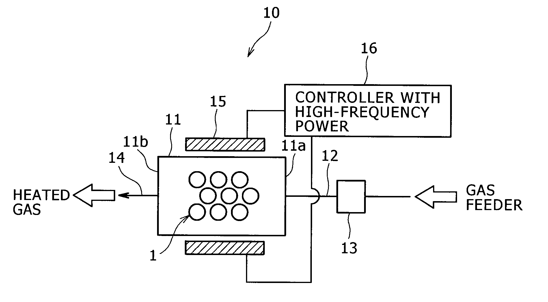
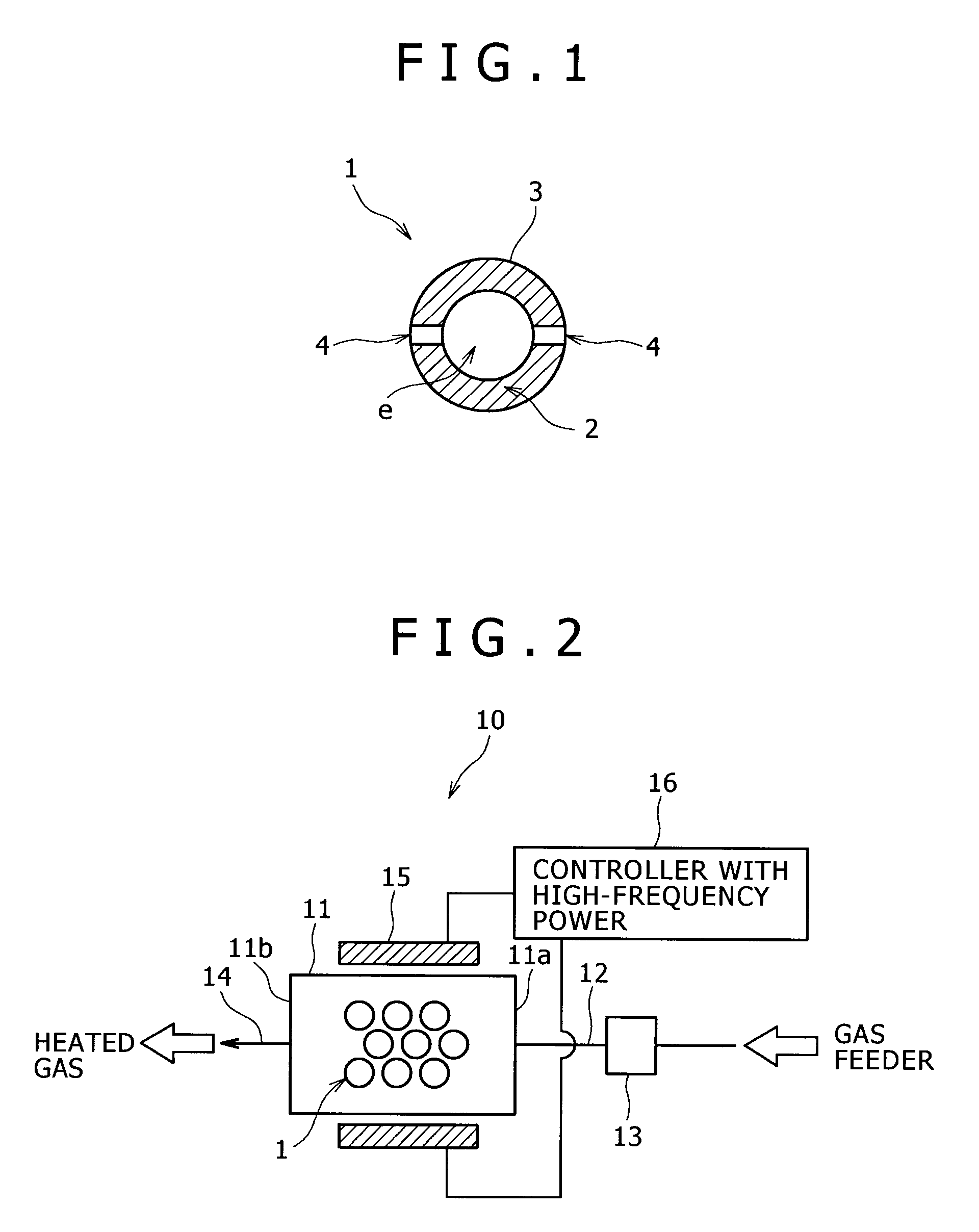
[0060]1-1. Fabrication of Inductive Heating Elements Composed of Glassy Carbon

[0061]Inductive heating elements composed of glassy carbon were fabricated in the following manner using a commercially available liquid phenolic resin (supplied from Gunei Chemical Industry Co., Ltd. under the trade name of PL-4804) as a material.

[0062]Initially, the resin was placed into a mold having a semi-spherical cavity with a radius of 15 mm and was held at 80° C. for twenty hours to semi-cure the resin, followed by removing the mold. Thus, a solid semi-spherical molded phenolic resin article having a radius of 15 mm was obtained.

[0063]Next, the molded article was hollowed to form a semispherical cavity having a radius of 12 mm concentrically with the outer periphery of the molded article. Thus, a semispherical hollow molded phenolic resin article having an outer diameter of 30 mm and a wall thickness of 3 mm was obtained.

[0064]Two semispherical hollow molded phenolic resin articles fabricated as a...

example 2

[0083]A spherical part having an outer diameter 25 mm was cut from a commercially available isotropic graphite material, and a silica layer about 5 μm thick was applied to the spherical part by the procedure of Example 1.

[0084]A steam heating test was conducted using the same flow gas heating system under the same condition as Example 1, except for using the spherical part having an insulating layer. The steam temperature at the outlet of the heating element casing was 325° C., indicating that the steam temperature was elevated through heating by 175° C.


PUM

PropertyMeasurementUnit
thicknessaaaaaaaaaa
radiusaaaaaaaaaa
radiusaaaaaaaaaa

Abstract

An inductive heating element includes a substrate and an insulating layer covering the substrate. The substrate contains a carbonaceous material such as glassy carbon. The inductive heating element effectively exchanges heat with a flowing gas to be heated and thereby efficiently heat the gas.

Description

BACKGROUND OF THE INVENTION[0001]1. Field of the Invention[0002]The present invention relates to inductive heating elements for use in gas heating systems for inductively heating gasses and other substances in processes for fabricating semiconductor devices.[0003]2. Description of the Related Art[0004]According to induction heating, an article to be heated (herein after also briefly referred to as “target”) is heated in the following manner. An induced current occurs in an electroconductive heating element by the action of a high-frequency coil, the induced current makes the heating element to liberate Joule's heat, and the Joule's heat elevates the temperature of the target. When the target is a gas such as water vapor (steam), air, or a hydrocarbon gas, the gas is allowed to flow through a heating system including the heating element.[0005]Systems for heating gases using the induction heating should satisfy following conditions (a), (b), and (c):[0006](a) the systems can efficient...

Claims


Application Information

Patent Timeline
Patent Type & Authority Applications(United States)
IPC IPC(8): H05B6/00H05B6/02H05B6/10
CPCH05B6/36
Inventor HAMAGUCHI, MAKIFUJIURA, TAKAYASU
Owner KOBE STEEL LTD
Features
  • Generate Ideas
  • Intellectual Property
  • Life Sciences
  • Materials
  • Tech Scout
  • Unparalleled Data Quality
  • Higher Quality Content
  • 60% Fewer Hallucinations
Learn More