
Method Of and System For Setting Laser Processing Conditions, Laser Processing System, Computer Program For Setting Laser Processing Conditions, Computer Readable Medium and Recording Device On Which Laser Processing Conditions Are Recorded

a laser processing and laser processing technology, applied in the field of laser processing systems, can solve the problems of optical readers encountering read errors and the read rate of such optical readers deteriorate, and achieve the effect of preventing the pattern from declining its readability and high read ra

Active Publication Date: 2008-01-17
KEYENCE
View PDF39 Cites 30 Cited by
  • Summary
  • Abstract
  • Description
  • Claims
  • Application Information

AI Technical Summary

Benefits of technology

[0006] It is therefore an object of the present invention to provide a method of and a system for laser processing condition setting which enables optical readers to read a processed pattern on three-dimensional work surfaces with an enhanced read rate.
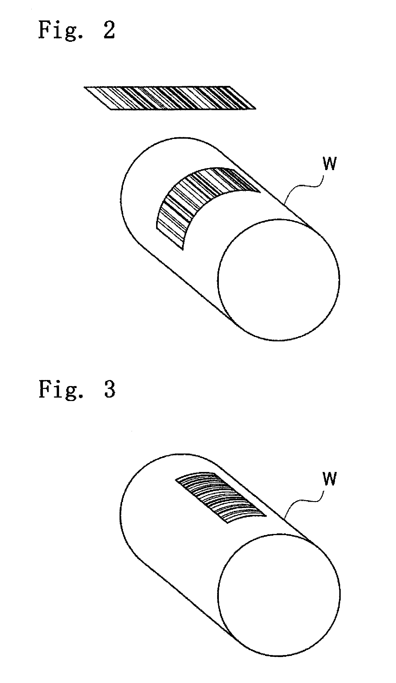
[0015] According to the present invention, since an orthogonal projection of a pattern applied even to a tree-dimensional work surface is identical with an original pattern, the optical reader is enabled to read the pattern on the work surface at a high read rate. Furthermore, a pattern can be printed without density gradient by varying or increasing scanline density, the pattern is prevented from declining its readability.

Problems solved by technology

However, when reading such a print pattern on a curved work surface by an optical barcode reader, an optical 2D code reader or an image recognition equipment, a read rate of such an optical reader deteriorates due to deformation of the print pattern which occurs according to an occurrence of an angle of an optical axis of the optical reader with a normal to the work surface.
If an angle of the optical axis of the optical reader with a normal to a work surface becomes large enough to be measurable, the optical reader encounters read errors.
However, many objects or work surfaces impose constrains on printing areas, which is of a major problem in the laser processing system.

Method used


Image

  • Method Of and System For Setting Laser Processing Conditions, Laser Processing System, Computer Program For Setting Laser Processing Conditions, Computer Readable Medium and Recording Device On Which Laser Processing Conditions Are Recorded
  • Method Of and System For Setting Laser Processing Conditions, Laser Processing System, Computer Program For Setting Laser Processing Conditions, Computer Readable Medium and Recording Device On Which Laser Processing Conditions Are Recorded
  • Method Of and System For Setting Laser Processing Conditions, Laser Processing System, Computer Program For Setting Laser Processing Conditions, Computer Readable Medium and Recording Device On Which Laser Processing Conditions Are Recorded

Examples


Embodiment Construction

[0054] Hereinafter, embodiments of the present invention will be concretely described with reference to the accompanying drawings, Although the following description is directed to a method of and a system for setting processing such as printing or marking including characters, symbols and graphics on work with a laser beam, a computer program for setting processing conditions for a laser processing conditions are recorded, nevertheless, the it should be appreciated that the present invention has broader applications and is not limited to this particular embodiments.

[0055] Further, in the following description, various changes and modifications may be made in the form, size, relative arrangement of constituent components and means of the described system and apparatus unless otherwise specified distinctively. It is intended that all matter contained in the description and as shown in the accompanying drawings shall be interpreted as illustrative and not in a limiting sense unless o...


PUM

PropertyMeasurementUnit
Angleaaaaaaaaaa
Densityaaaaaaaaaa
Radiusaaaaaaaaaa

Abstract

A laser method of printing a pattern on works which is read at a high read rate by optical readers and a system for implementing the laser processing method are described. print pattern data is generated based on printing conditions including at least an original print pattern such as a character string that are specified by users and then converted into data representing an actual print pattern to be actually printed on works according to a three dimensional profile of the works so that an orthogonal projection of that actual print pattern is identical with the original print pattern.

Description

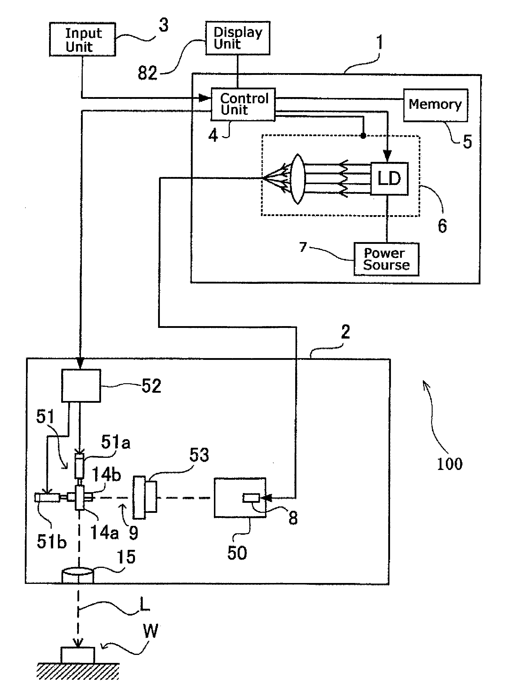
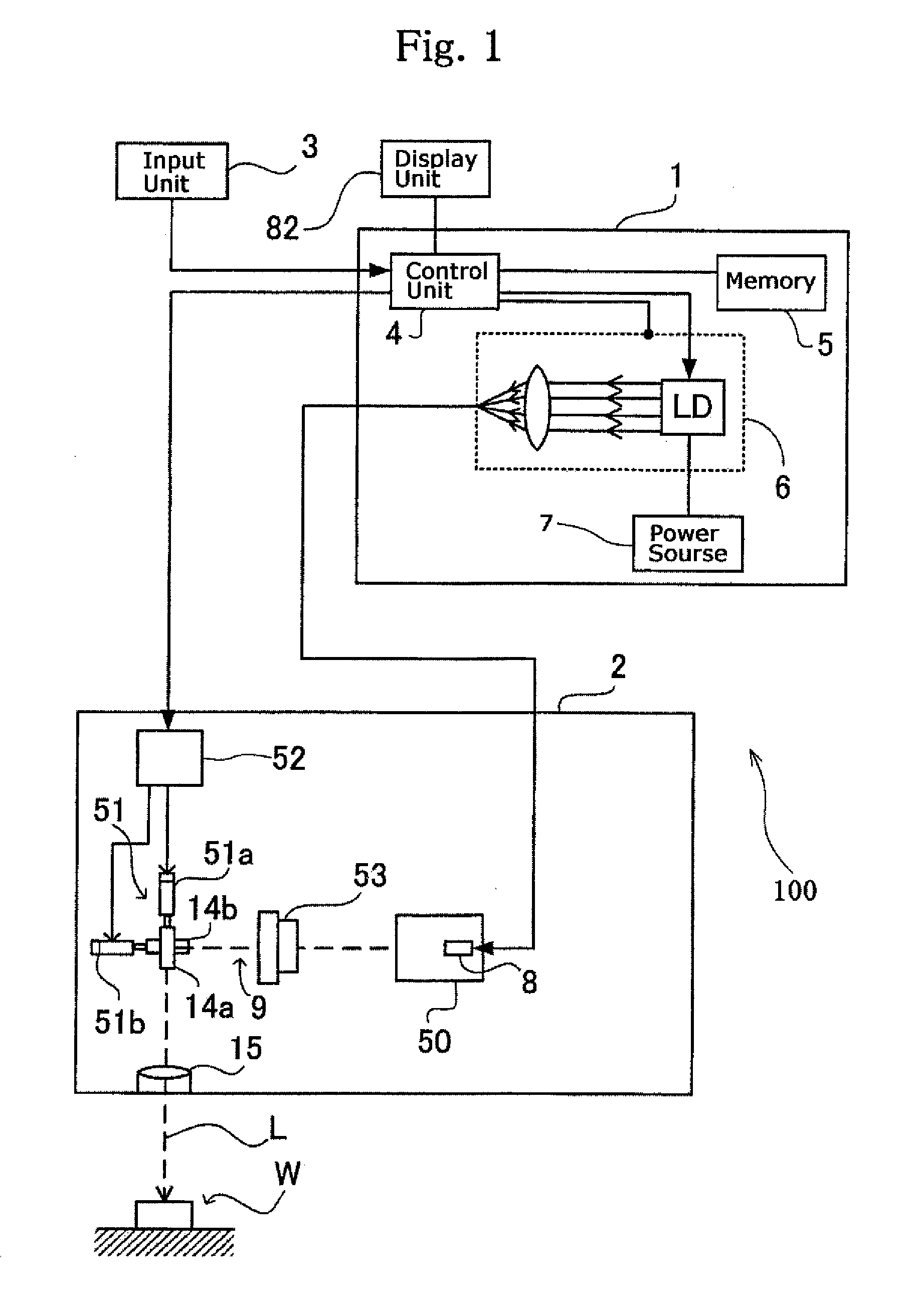
BACKGROUND OF THE INVENTION [0001] 1. Filed of the invention [0002] The present invention relates to a method of and a system for setting processing conditions of a laser processing system such as a laser marker which performs processing such as printing or marking including characters, symbols and graphics on work with a laser beam, a computer program for setting processing conditions for a laser processing system, a computer-readable recording medium or device on which laser processing conditions are recorded. [0003] 2. Description of Related Art [0004] A laser processing system scans a given scan field of a subject surface of works (work surfaces) such as components and finished products with a laser beam to apply processing, such as printing and marking of characters, symbols and / or graphics, to the work surfaces. Referring to FIG. 1 for the purpose of providing a brief description of a configuration of a laser processing system by way of example, the laser processing system com...

Claims


Application Information

Patent Timeline
IPC IPC(8): G06K7/10B23K26/00B23K26/03
CPCG06K1/121G06K19/00
Inventor IDAKA, MAMORU
Owner KEYENCE
Learn More