Joint structure of pipe
- Summary
- Abstract
- Description
- Claims
- Application Information
AI Technical Summary
Benefits of technology
Problems solved by technology
Method used
Image

Examples
Embodiment Construction
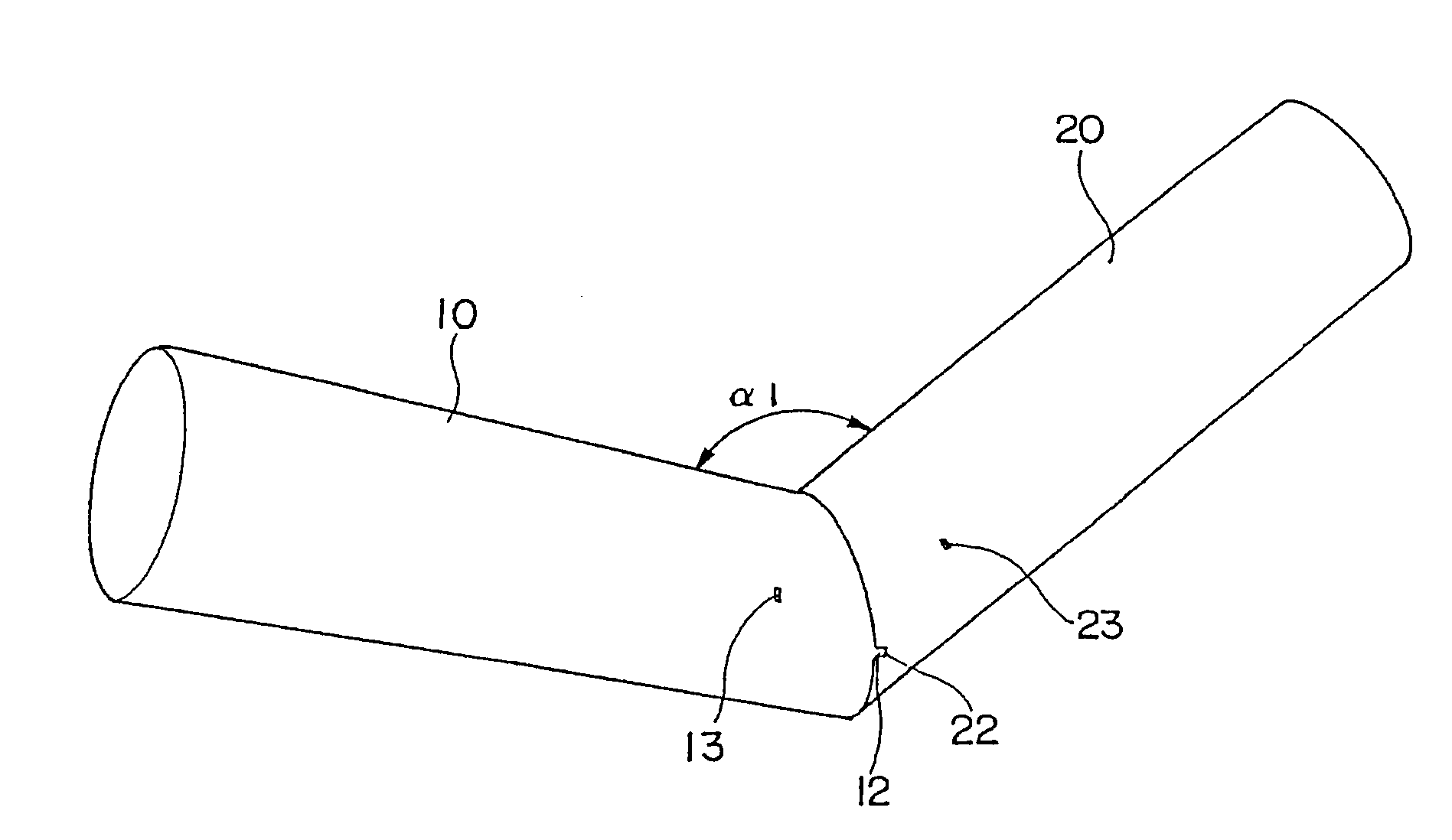
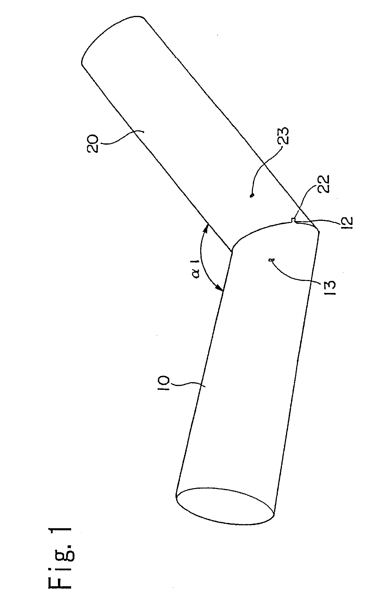
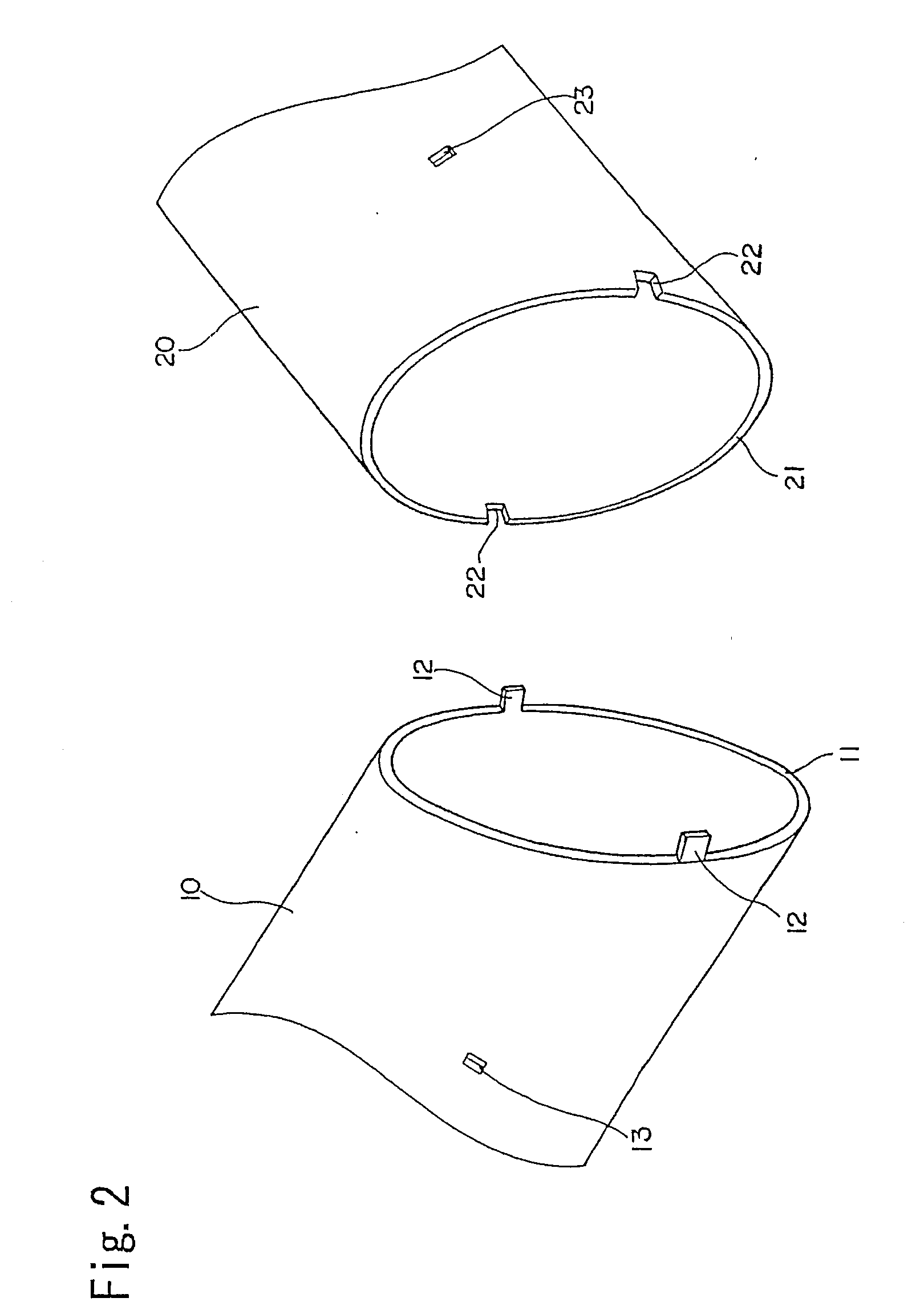
[0025]FIG. 1 is a perspective view showing a joint structure of a pipe of the present invention, and FIG. 2 is an explanatory view showing the detail of a joint portion.
[0026] As shown in FIG. 1, a first pipe 10 and a second pipe 20 are directly joined to each other at their ends. And both the pipes 10, 20 are joined having an angle α1.
[0027] As shown in FIG. 2, the first pipe 10 has a joined end face 11 obtained by laser machining at a predetermined angle to an axis and tenons 12 projecting from the joined end face 11. In this preferred embodiment, the number of tenons 12 is 2, but the number, location and the like of the tenons may be selected as appropriate.
[0028] On a periphery of the first pipe 10, mortices 13 for receiving tenons of a third pipe and a fourth pipe, which will be described later, are provided.
[0029] The second pipe 20 has a joined end face 21 obtained by laser machining at a predetermined angle to an axis and a mortice 22 cut from the joined end face 21. Thi...
PUM
 Abstract
Description
Claims
Application Information
 - Generate Ideas
- Intellectual Property
- Life Sciences
- Materials
- Tech Scout
- Unparalleled Data Quality
- Higher Quality Content
- 60% Fewer Hallucinations
Browse by: Latest US Patents, China's latest patents, Technical Efficacy Thesaurus, Application Domain, Technology Topic, Popular Technical Reports.
© 2025 PatSnap. All rights reserved.Legal|Privacy policy|Modern Slavery Act Transparency Statement|Sitemap|About US| Contact US: help@patsnap.com