
Method and apparatus for utilizing commutation sensors for speed and position control

Active Publication Date: 2008-01-17
EXLAR CORP
View PDF9 Cites 34 Cited by
  • Summary
  • Abstract
  • Description
  • Claims
  • Application Information

AI Technical Summary

Benefits of technology

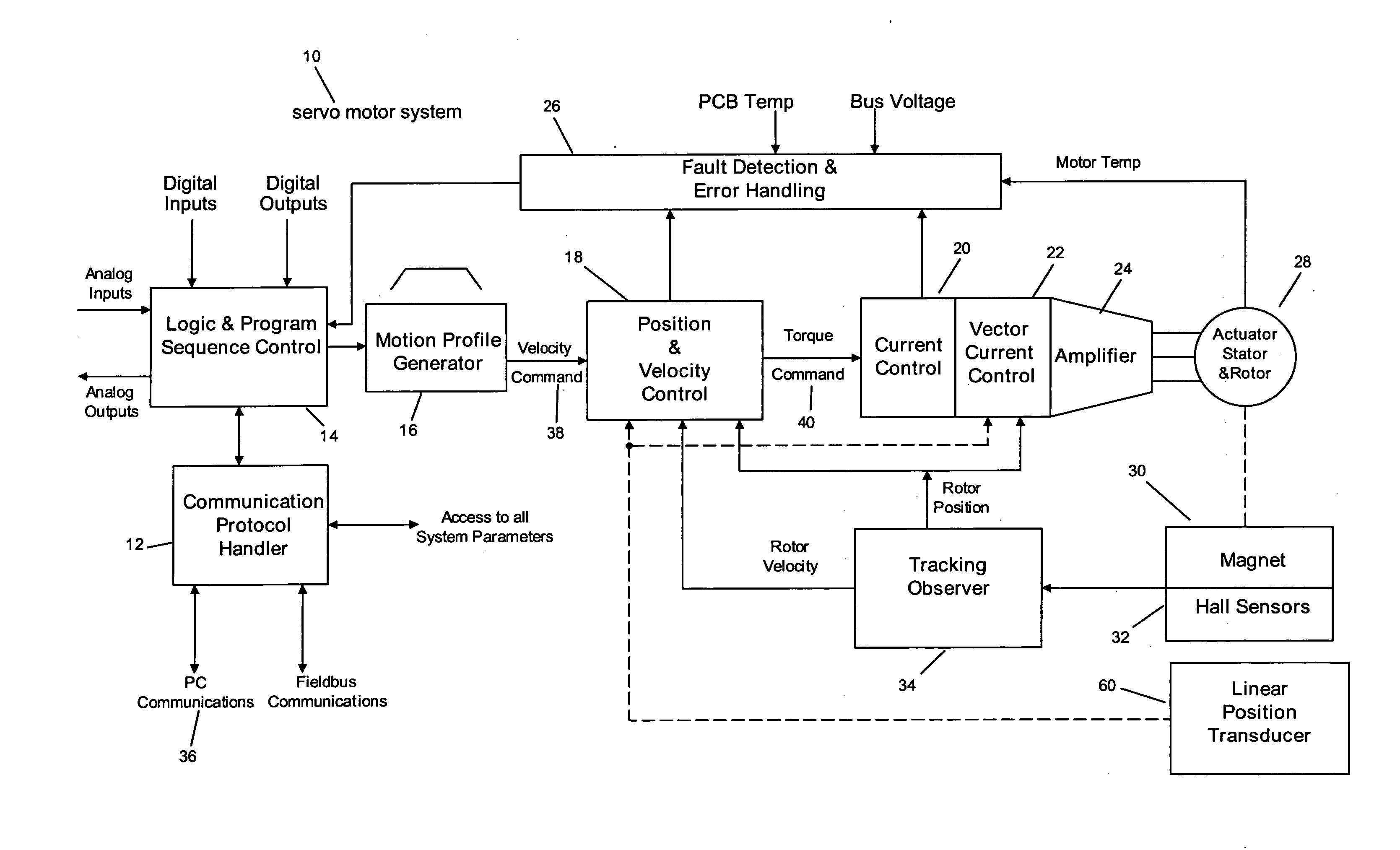
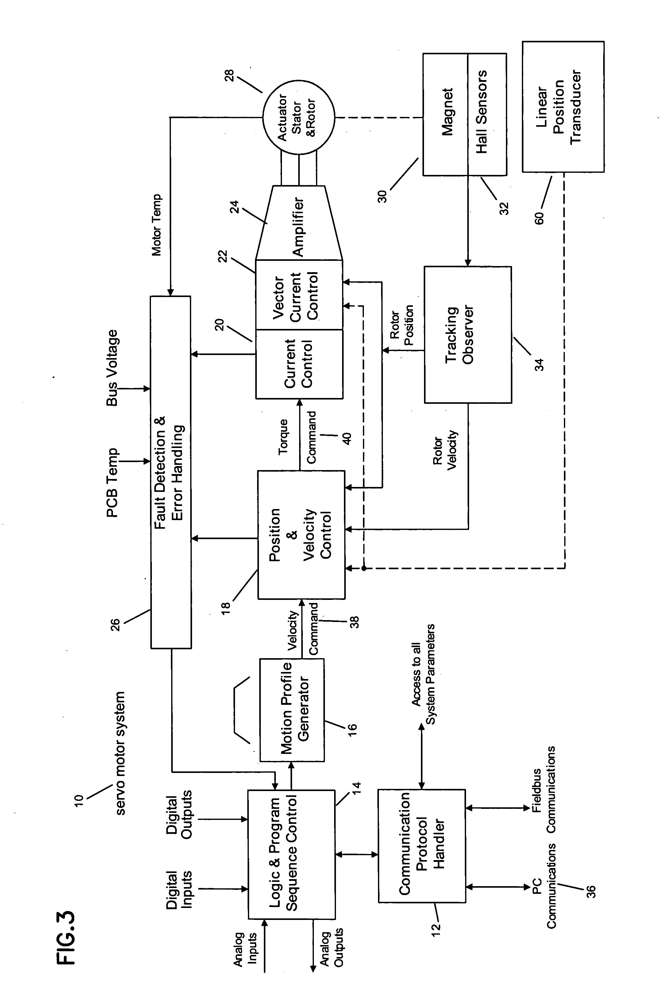
[0010] The present invention provides a solution to the drawbacks of the prior art by providing a linear actuator system which utilizes inexpensive sensors to provide both commutation and the position information necessary to control the system. To do so, a preferred system constructed according to the principles of the present invention utilize one or more magnets mounted on the rotor of the motor / actuator and one or more analog Hall Effect sensors mounted on the stator of the of the motor to provide the necessary feedback for both control of the rotor and position / speed control.
[0012] Advantages of the present invention include a lower cost than either an encoder or a resolver based system as well as smaller size and lower weight. For example, a magnet and the necessary hall sensor(s) are low cost items compared to a resolver or encoder. Also the, the magnetic feedback subsystem uses fewer connections.
[0013] Another feature of the present invention is that the controller (and other electronics may be integrated into the housing of the motor or actuator. This provides a compact, efficient system for use in a number of applications.

Problems solved by technology

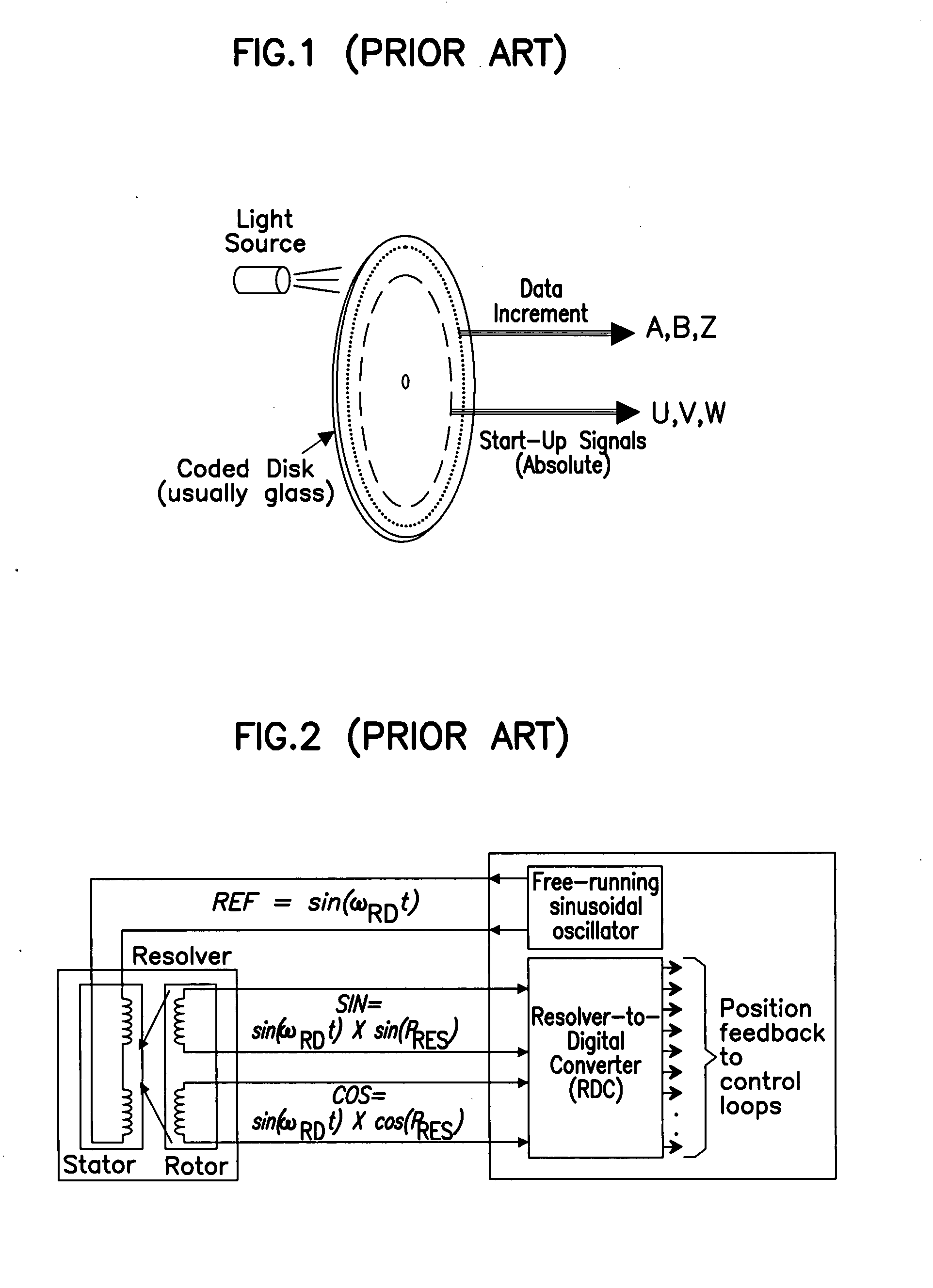
Encoder and resolver based systems are complex systems resulting in high cost components, requiring a larger number of connections, and adding to the overall length and weight of the motor.

Method used


Image

  • Method and apparatus for utilizing commutation sensors for speed and position control
  • Method and apparatus for utilizing commutation sensors for speed and position control
  • Method and apparatus for utilizing commutation sensors for speed and position control

Examples


working example

[0077] One example of an operational application of the servo system 10 of the present invention may be a clamping application. The application may allow for two move positions: 1) clamped (4.5 inch position) and 2) unclamped (0.0 inch position). In this application, at the clamped position, the actuator 28 is required to move up against a hard stop at the 4.5 inch position and hold it with a specified force or current. To avoid hitting the hard stop at full speed, a ‘feed type’ move is used, which reduces the velocity to the feed velocity at the specified position. Once the hard stop is hit, the actuator 28 holds the force until the retract move is activated

[0078] Referring now to FIG. 14, using the PC set-up software 52, the user assigns the above input and output functions to the I / O points he / she has wired to. The inputs may be: 1) “Clamp” and 2) “Unclamp”. The outputs may be: 1) “Ready”, 2) “Clamped”, or 3) “Unclamped”. Home mode is set to perform an automatic home cycle on po...


PUM


Abstract

One or more magnets are mounted on the rotor of a motor / actuator and analog Hall Effect sensors are mounted on the stator of the motor actuator to provide the necessary feedback for both speed and position control of the rotor. The feedback system includes signal conditioning circuitry for conditioning the sinusoidal signal produced by the magnet and the Hall Effect sensors and a tracking converter observer algorithm executing on the system microprocessor to produce controlled motion. The controller (and other electronics) may be integrated into the housing of the motor or actuator to provide a compact, efficient system for use in a number of applications.

Description

CROSS-REFERENCE TO RELATED APPLICATIONS [0001] This application claims the benefit of U.S. Provisional Application No. 60 / 817,841, filed Jun. 29, 2006. Such application is incorporated herein by reference.FIELD OF THE INVENTION [0002] The invention relates generally to the field of rotary to linear actuators; more particularly to a servo feedback system; and more particularly still to a servo system employing commutation sensors for both speed and position control. BACKGROUND OF THE INVENTION [0003] In brushless motor systems the motor rotor position must be sensed for commutation and position / speed control. Traditionally this has been accomplished with a combination of digital Hall sensors & incremental encoders, absolute encoders or resolvers. [0004] Historically in brushless motor systems, commutation sensors have been used for sensing the relative position of the rotor to the stator allowing the control to generate the magnetic fields required to produce motion of the rotor. Add...

Claims


Application Information

Patent Timeline
IPC IPC(8): G05B1/06
CPCH02P6/16
Inventor WIEGERS, JOHN P.HINER, ERIC A.ZERULL, WILLIAM JOSEPH
Owner EXLAR CORP
Learn More