Side-emitting light-emitting element and packaging lens thereof

Inactive Publication Date: 2008-01-17
CORETRONIC
View PDF3 Cites 12 Cited by
  • Summary
  • Abstract
  • Description
  • Claims
  • Application Information

AI Technical Summary

Benefits of technology

[0008]A side-emitting light-emitting element and a packaging lens thereof according to the present invention reduce the light loss occurring in a refractive surface and avoid that the total reflection resulting from a too large incident angle.
[0009]In a preferred embodiment of a side-emitting light-emitting element and a packaging lens thereof according to the present invention, a first refractive surface has a zigzag surface, and a light reflected by the reflective surface vertically penetrat

Problems solved by technology

First, when the light reflected by the reflective surface 11 is not incident the first refractive surface 12 in an incident angle with a right angle, and it results in the energy loss; further, when the incident angle is too great it brings about a total reflection.
Second, a portion of the light reflected by the first refractive 12 penetrates the refle

Method used


Image

  • Side-emitting light-emitting element and packaging lens thereof
  • Side-emitting light-emitting element and packaging lens thereof
  • Side-emitting light-emitting element and packaging lens thereof

Examples


Embodiment Construction

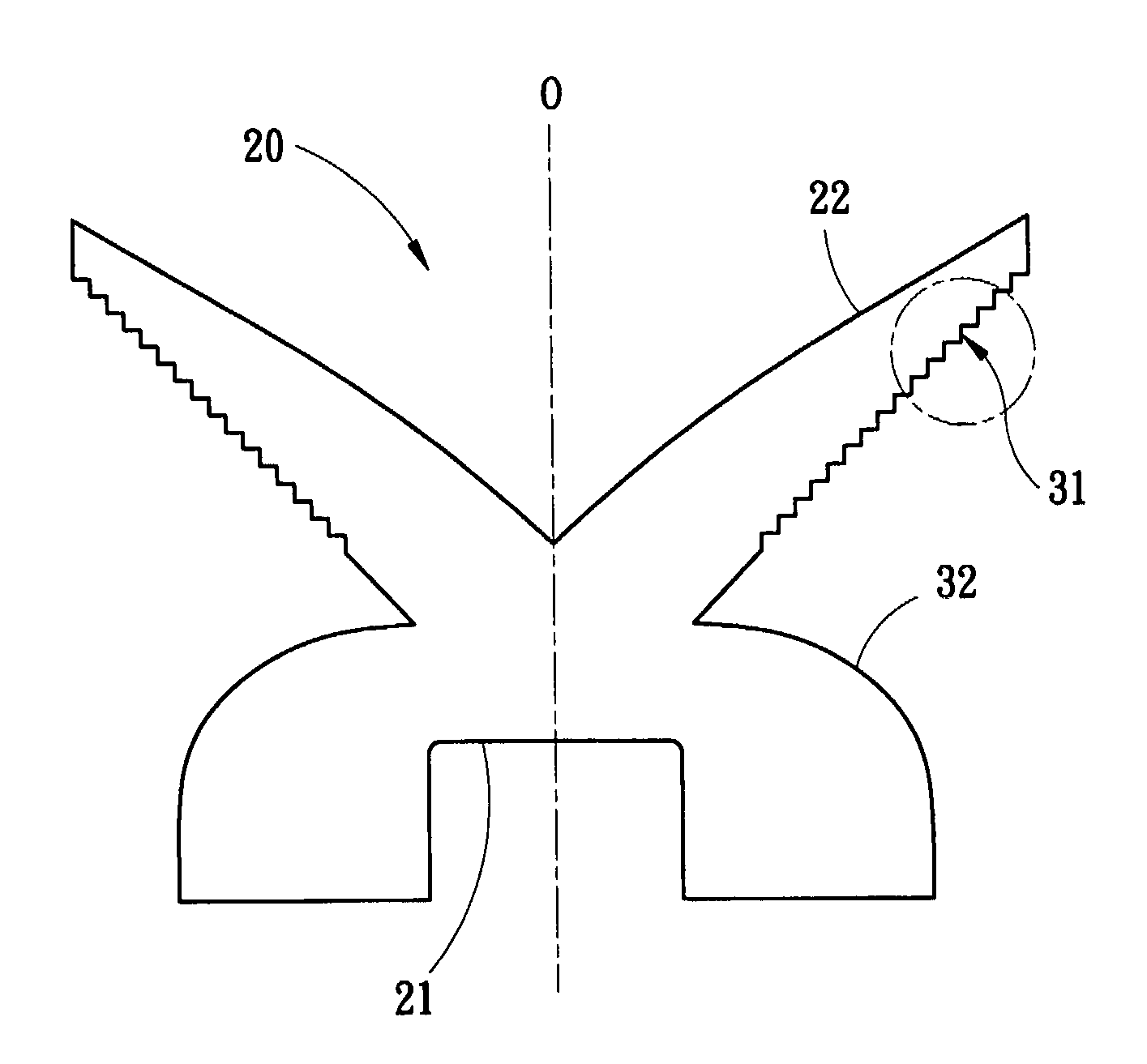
[0020]Please refer to FIG. 4A showing a packaging lens of the preferred embodiment according to the present invention. A profile of the packaging lens 20 is symmetrical with respect to an optical axis 0. Therefore, the structure in one side of the optical axis 0 is used for exemplifying the packaging lens 20 according to the present invention in the following description. In a preferred embodiment, the packaging lens 20 comprises an incident surface 21, a reflective surface 22, a first refractive surface 31 and a second refractive surface 32. The optical axis 0 passes through the incident surface 21. The reflective surface 22 is connected to the first refractive surface 31. The second refractive surface 32 is connected to the first refractive surface 31 and the incident surface 21. The reflective surface 22 is a surface of total internal reflection (TIR). The shape of the reflective surface 22 is designed to be that the reflective surface 22 reflects a light from a light source to p...


PUM


Abstract

A side-emitting light-emitting element and a packaging lens thereof, wherein the packaging lens comprises an incident surface, a reflective surface, a first refractive surface, and a second refractive surface. The first refractive surface has zigzag surfaces. After a light from a light source enters into the packaging lens through the incident surface, a portion of the light is reflected by the reflective surface to the first refractive surface via total internal reflection to vertically penetrate the first refractive surface and then proceeds along a first optical path. The other portion of the light is refracted by the second refractive surface to penetrate the second refractive surface and then proceeds along a second optical path, which is parallel to the first optical path. A zigzag surface of the first refractive surface avoids from undesired lights reflected by the first refractive surface.

Description

FIELD OF THE INVENTION[0001]The present invention relates to a light-emitting element, particularly to a side-emitting light-emitting element and a packaging lens thereof.BACKGROUND OF THE INVENTION[0002]As shown in FIG. 1A, a light-emitting path of conventional light-emitting elements, such as the light-emitting diode (LED) 15, is perpendicular to a light-emitting surface of the light-emitting elements, and the energy distribution thereof is Lambert's type. The conventional light-emitting elements are usually applied to traffic signals, illuminators or other guide signs. However, as shown in FIG. 1B, when multiple LEDs 15 and 15′ are arranged together to mix optical properties, such as mixing light intensity or light color. The mixing effect can be obtained at a given distance away from the light-emitting surface. An invalid distance D1 is the given distance where the mixing effect does not appear. If the light distribution pattern of the emitted light can be flattened, the invalid...

Claims


Application Information

Patent Timeline
IPC IPC(8): F21V5/00
CPCF21V5/04F21V7/0091G02B19/0061G02B19/0071G02B19/0028F21Y2101/02F21Y2115/10
Inventor SHIAU, TZENG-KECHOU, WEN-BINHOU, TENG-CHAO
Owner CORETRONIC
Why Eureka
Try Eureka