Channel-switching multicast distribution apparatus and method, and multicast reception apparatus

Inactive Publication Date: 2008-01-17
KDDI CORP
View PDF6 Cites 14 Cited by
  • Summary
  • Abstract
  • Description
  • Claims
  • Application Information

AI Technical Summary

Benefits of technology

[0045]In accordance with the present invention, it is possible to (i) contribute to quick channel switching in the Internet protocol t

Problems solved by technology

However, with respect to the channel switching, delay is generated in starting the reproduction of a program in the new channel, due to necessity of data storage into the IPTV reception device, or the like.
For example, (i) storage of data for decoding a digital-compression-encoded video content, (ii) storage of data for decoding error-correction codes which are used for correcting transmission errors, (iii) reprodu

Method used


Image

  • Channel-switching multicast distribution apparatus and method, and multicast reception apparatus
  • Channel-switching multicast distribution apparatus and method, and multicast reception apparatus
  • Channel-switching multicast distribution apparatus and method, and multicast reception apparatus

Examples


first embodiment

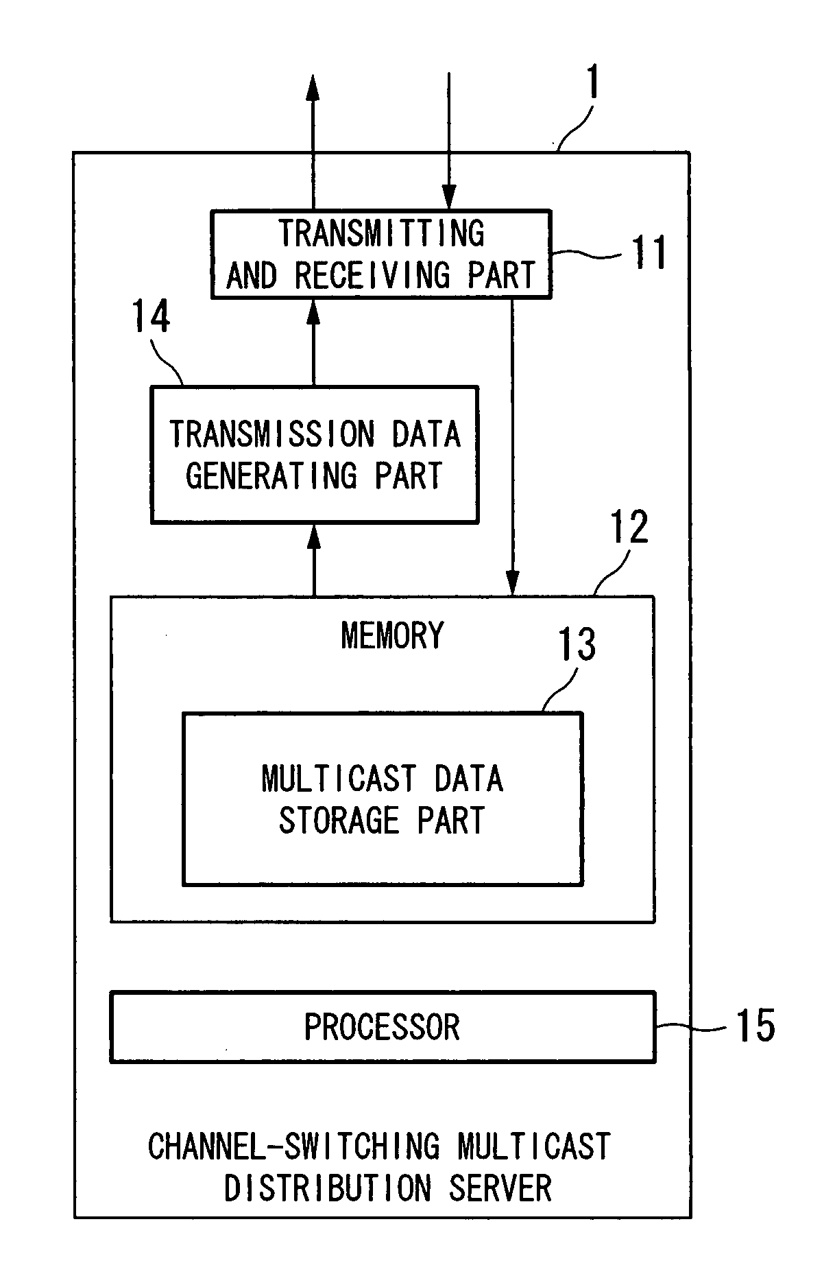
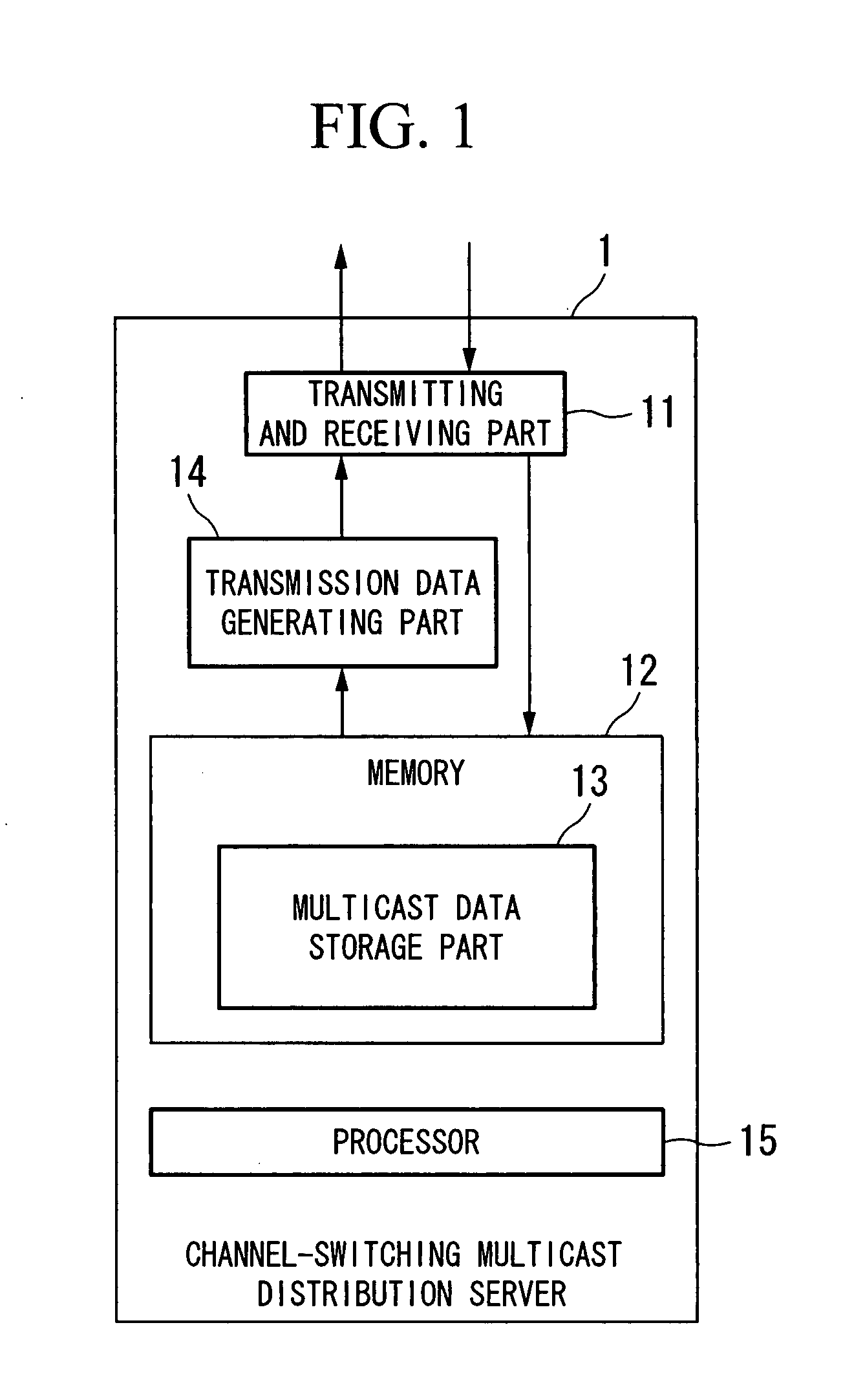
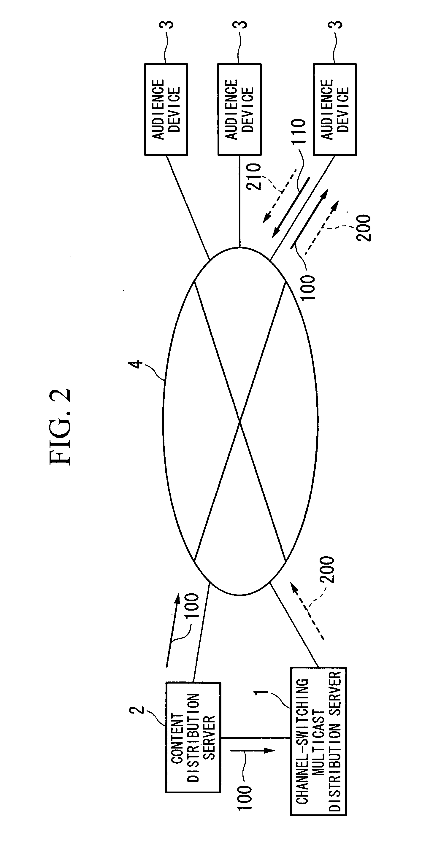
[0059]FIG. 2 is a block diagram showing the general structure of an IPTV system with respect to a first embodiment of the present invention.

[0060]In FIG. 2, the channel-switching multicast distribution server 1, a content distribution server 2, and audience devices 3 are connected to a communication network 4 accommodated to IP multicast operation. In addition, the structural elements 1 to 3 and the communication network 4 are accommodated to IGMP (Internet group management protocol) which is a well-known IP multicast method.

[0061]The content distribution server 2 distributes each program, provided by the IPTV, by using a multicast group (“multicast Gp”) 100 via the communication network 4 to relevant audience devices 3. The content distribution server 2 can provide a plurality of channels, and the multicast Gp 100 is assigned to each channel. The multicast Gp 100 of each channel has a unique multicast address.

[0062]The channel-switching multicast distribution server 1 directly rece...

second embodiment

[0076]FIG. 5 is a block diagram showing the general structure of the IPTV system with respect to a second embodiment of the present invention.

[0077]As shown in FIG. 5, in the second embodiment, each of a plurality of the channel-switching multicast distribution server 1 is connected to a router 5, which is connected to the communication network 4. The router 5 is also connected to an audience device 3.

[0078]In FIG. 5, each channel-switching multicast distribution server 1 has two ports: (i) one is for monitoring communication of the audience device 3 by way of the router 5, and receiving data, sent from the audience device 3, via the router 5, and (ii) the other is used for general communication, and is connected to a port of the router 5, which belongs to the same network segment to which a port (of the router 5) for accessing the communication network 4 belongs.

[0079]Similar to the first embodiment, the channel-switching multicast distribution server 1 delays multicast data (recei...


PUM


Abstract

A channel-switching multicast distribution apparatus in a system for providing channels by multicast. The apparatus includes a device for receiving multicast data of a first multicast group for a first channel; a device for storing the received multicast data; a delaying device for reading the stored multicast data, and delaying the data by a predetermined time; and a transmission device for transmitting the delayed data through a second multicast group for performing channel switching so as to select the first channel. Instead of the delaying device and the transmission device, a data rearranging device for reading the stored multicast data, and rearranging the data so as to change the order of packets thereof; and a transmission device for transmitting the rearranged data through a second multicast group for performing channel switching so as to select the first channel may be provided.

Description

BACKGROUND OF THE INVENTION[0001]1. Field of the Invention[0002]The present invention relates to a channel-switching multicast distribution apparatus, a multicast reception apparatus, and a channel-switching multicast distribution method.[0003]Priority is claimed on Japanese Patent Application No. 2006-191462, filed Jul. 12, 2006, the content of which is incorporated herein by reference.[0004]2. Description of the Related Art[0005]Due to recent improvement of broadband communication networks, a demand for distributing large amounts of video content via IP (Internet protocol) networks has been increased. In such video-content distribution services, when distribution time is predetermined, the same video content can be efficiently and simultaneously distributed to a large number of audiences. For example, a telecast using the Internet (called “Internet protocol television (IPTV)” below) provides a service of simultaneously distributing a plurality of TV programs through a plurality of...

Claims


Application Information

Patent Timeline
IPC IPC(8): H04B7/212H04L45/16H04N7/173H04N21/238H04N21/241H04N21/262
CPCH04L12/1881H04L12/185
Inventor SASAKI, CHIKARAHASEGAWA, TERUYUKITAGAMI, ATSUSHI
Owner KDDI CORP
Why Eureka
Try Eureka