
Earguard monitoring system

a monitoring system and earguard technology, applied in the field of earguard monitoring system, can solve the problems of ear damage, permanent hearing impairment not only increasing in the general population, and the possibility of hearing damag

Active Publication Date: 2008-01-17
STATON TECHIYA LLC
View PDF28 Cites 33 Cited by
  • Summary
  • Abstract
  • Description
  • Claims
  • Application Information

AI Technical Summary

Benefits of technology

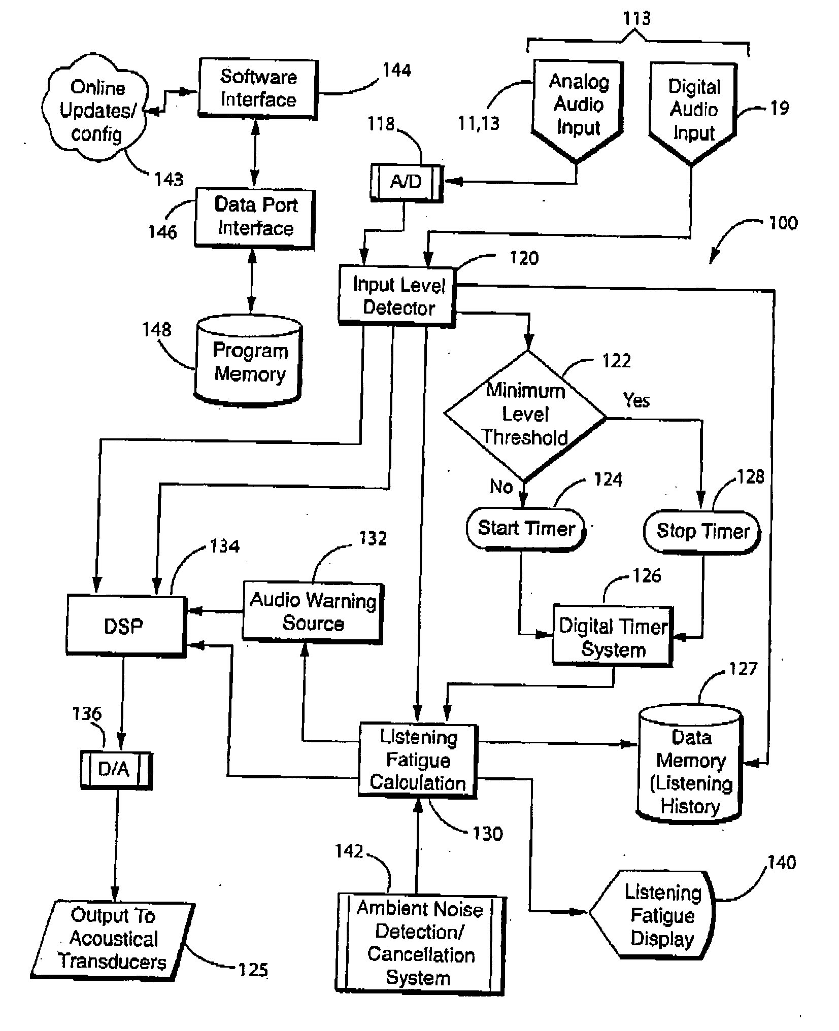
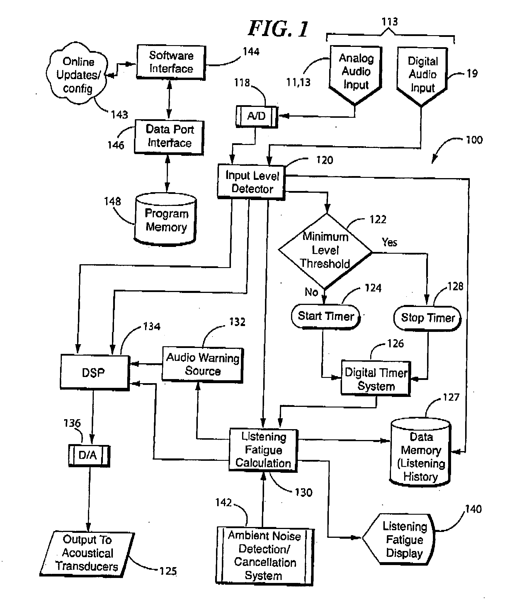
[0011] At least one exemplary embodiment is directed to a SPL monitoring system comprising: an audio transducer, where the audio transducer is configured to receive sound pressure, and where the audio transducer outputs a plurality of electronic signals, where each signal represents sound pressure levels (SPL) for a particular frequency band; a logic circuit, where time is broken into increments of time, where the logic circuit measures and stores in a memory storage system an exposure time duration when a signal's SPL exceeds a threshold value for the particular frequency band of the signal and stores the SPL level associated with each increment of time in the exposure time duration, and where the logic circuit measures and stores a recovery time duration when the signal's SPL drops below the threshold value for the particular frequency band of the signal and stores the SPL level associated with each increment of time in the recovery time duration, where the logic circuit calculates over an averaging time interval an average SPL dose within the averaging time interval, and where the logic circuit calculates a safe time duration over which a user can receive current sound pressure values; and an indicator element, where the indicator element produces a notification when an indicator level occurs, where the indicator level is at least one of: when the safe time duration has been exceeded; when a listening duration is within a certain percentage range of the safe time duration; when a listening duration is within various levels, where each level is represented by an indicator color and where each level represents a percentage range of the safe time duration; when the power is low; and when at least one feature is not working.

Problems solved by technology

Studies show that ear damage, leading to permanent hearing impairment is not only increasing in the general population, but increasing at a significantly faster rate in younger populations.
The potential for hearing damage is a function of both the loudness and the duration of exposure to the sound stimulus.
Although hearing damage due to industrial or background noise exposure is more thoroughly understood, the risk of exposing one's self to excessive noise, especially with the use of headphones has also been recently studied.
These prior art devices have been less than satisfactory because they do not completely prevent high decibel noise from reaching the ear, and do not account for the duration of exposure to harmful sounds at the ear.
However, there is no monitoring of the noise over time to account for the cumulative effect.
Furthermore, there is no accounting for any restorative effects for sound pressure levels, which are healing to the ear rather than destructive.
However, the device does not take into account the cumulative effect of the noise or the effect of any restorative period.
This approach is ineffective as it does not take into account listening duration and the calculation of risk for auditory injury.
Other headphones are maximum-limited to produce levels that can still result in significant overexposure given enough time, or limit the user to levels, which may not be sufficient to achieve a short term listening level.
In the latter case, consumer acceptance for the protective gear could be severely limited and a product would fail to survive in a competitive market and therefore be of no use.
The limitation of this approach is that it gives no consideration to the duration of exposure, and again either the user's chosen listening level cannot be achieved because the maximum level is too limited, or the level is sufficient to allow the user access to high enough sound levels, but risk overexposure due to potential duration of use.
Additionally, related art systems fail to show, suggest, or teach a method for sharing an audio transmission amongst enabled devices over a wireless communications system.
Nor do the related art systems disclose a detailed registration process, through which the ear input SPL monitoring system can be customized for an individual user.

Method used


Image

  • Earguard monitoring system
  • Earguard monitoring system
  • Earguard monitoring system

Examples


Embodiment Construction

[0026] The following description of exemplary embodiment(s) is merely illustrative in nature and is in no way intended to limit the invention, its application, or uses.

[0027] The following description of at least one exemplary embodiment is merely illustrative in nature and is in no way intended to limit the invention, its application, or uses.

[0028] Processes, techniques, apparatus, and materials as known by one of ordinary skill in the relevant art may not be discussed in detail but are intended to be part of the enabling description where appropriate, for example closed cavity volume.

[0029] In all of the examples illustrated and discussed herein any specific values, for example the number of user's, particular type of wireless communication protocol, should be interpreted to be illustrative only and non limiting. Thus, other examples of the exemplary embodiments could have different values or use other protocols.

[0030] Notice that similar reference numerals and letters refer ...


PUM


Abstract

At least one exemplary embodiment is directed to A SPL monitoring system comprising: an audio transducer, where the audio transducer is configured to receive sound pressure; a logic circuit, where the logic circuit calculates a safe time duration over which a user can receive current sound pressure values; and an indicator element, where the indicator element produces a notification when an indicator level occurs. Furthermore at least on further exemplary embodiment is directed to an SPL monitoring information system comprising: a database stored, where the database includes data, such as a list of earpiece devices and associated instrument response functions where the logic circuit compares the request with the data in the database and retrieves the subset of data and sends it to the output control unit, where the output control unit sends the subset of data to the sending unit.

Description

CROSS-REFERENCE TO RELATED APPLICATIONS [0001] This Application is a Continuation in Part of patent application Ser. No. 11 / 757,152, filed 1 Jun. 2007 the disclosure of which is incorporated herein by reference in it's entirety, and additionally claims the priority benefit of Provisional Application No. 60 / 804,650 filed on Jun. 14, 2006 the disclosure of which is incorporated herein by reference in it's entirety as well.FIELD OF THE INVENTION [0002] The present invention relates to a system for monitoring the sound pressure levels at a listener's ear, and in particular, thought not exclusively, to monitoring the sound pressure levels over time and to utilize that information to reduce hearing damage. BACKGROUND OF THE INVENTION [0003] With the advent of an industrial society, people are exposed to noise pollution at greater and greater levels; both from background, such as street traffic, airplanes, construction sites and intentional exposure to high sound levels such as cell phones...

Claims


Application Information

Patent Timeline
Patent Type & Authority Applications(United States)
IPC IPC(8): A61B5/00
CPCG01H3/14H04R2460/15H04R29/008H04R3/007H04R29/00
Inventor GOLDSTEIN, STEVEN WAYNE
Owner STATON TECHIYA LLC
Learn More