Cache memory system

a memory system and cache technology, applied in the field of cache memory systems, can solve the problems of increasing the complexity and size of circuitry, reducing the utilization efficiency of cache memory, and increasing the complexity of circuitry, so as to prevent the occurrence of access conflict and reduce the cost of devices

Inactive Publication Date: 2008-01-17
PANASONIC CORP
View PDF6 Cites 13 Cited by
  • Summary
  • Abstract
  • Description
  • Claims
  • Application Information

AI Technical Summary

Benefits of technology

[0014]In the inventive cache memory system, since the identification information is stored in each of the cache lines, instruction cache and data cache are distinguishable by the cache line. It is thus possible to prevent the occurrence of access conflict between instruction processing and data processing.
[0015]According to the present invention, the identification information is used for cac...

Problems solved by technology

However, the presence of the two separate lines causes the utilization efficiency of the cache memories to be lowered and the circuitry to be increased in complexity and size.
However, in multiport memory multiplexed by cell units, wiring to each memory cell is multiplexed, causing the circuitry to become very complex to thereby significantly increase the cost as compared to single port memory.
Nevertheless, in ...

Method used


Image

  • Cache memory system
  • Cache memory system
  • Cache memory system

Examples


first embodiment

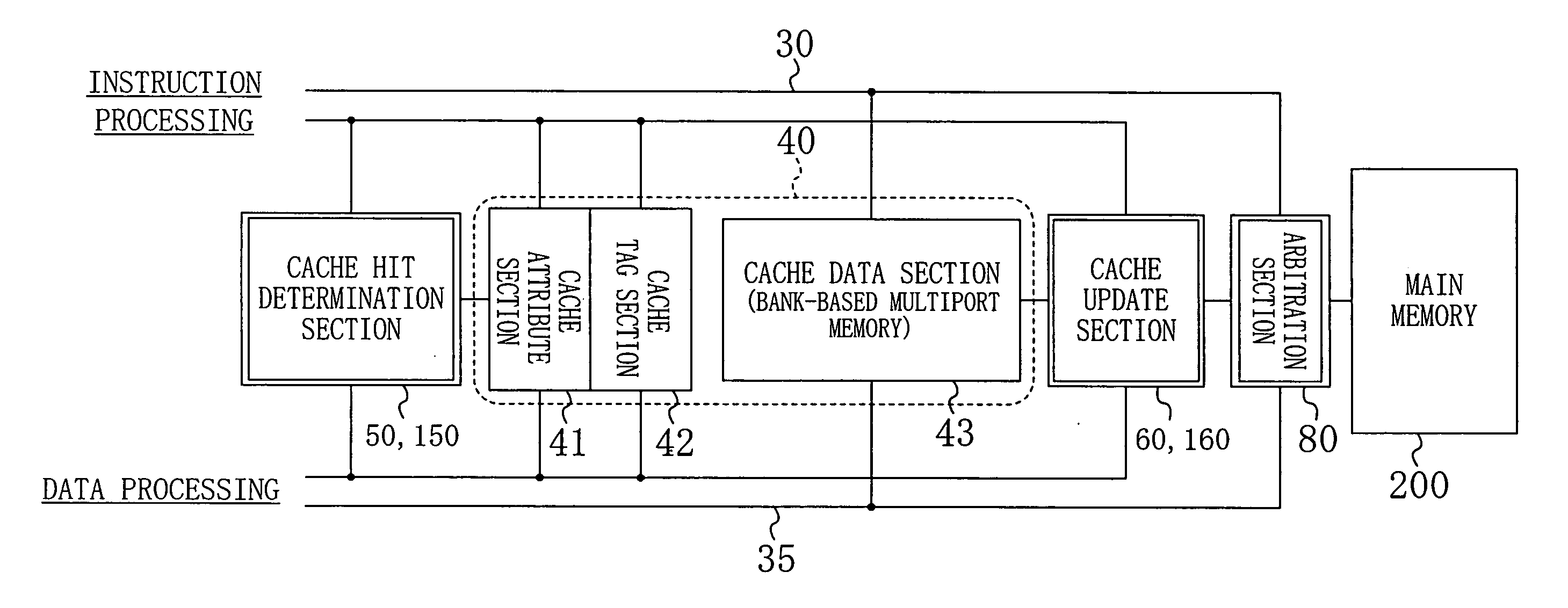
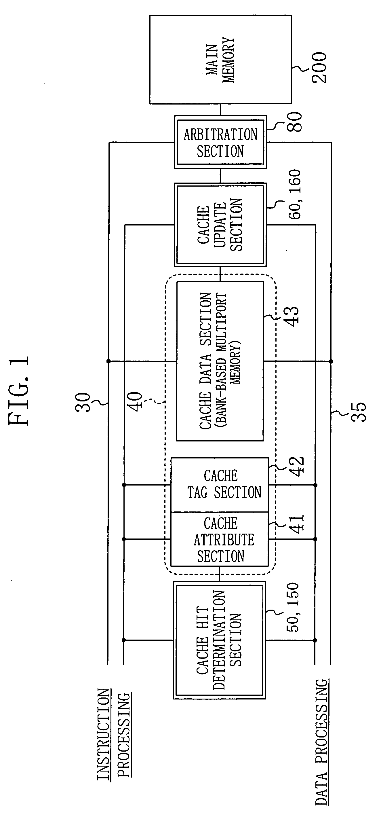
[0025]FIG. 1 is a block diagram illustrating the configuration of a cache memory system according to a first embodiment of the present invention. The cache memory system shown in FIG. 1 includes a cache memory 40, an instruction bus 30, a data bus 35, a cache hit determination section 50, a cache update section 60, and an arbitration section 80. The cache memory 40 includes a cache attribute section 41, a cache tag section 42, and a cache data section 43. The cache memory 40 includes a bank-based multiport memory and serves as a unified cache which is shared by instruction processing and data processing.

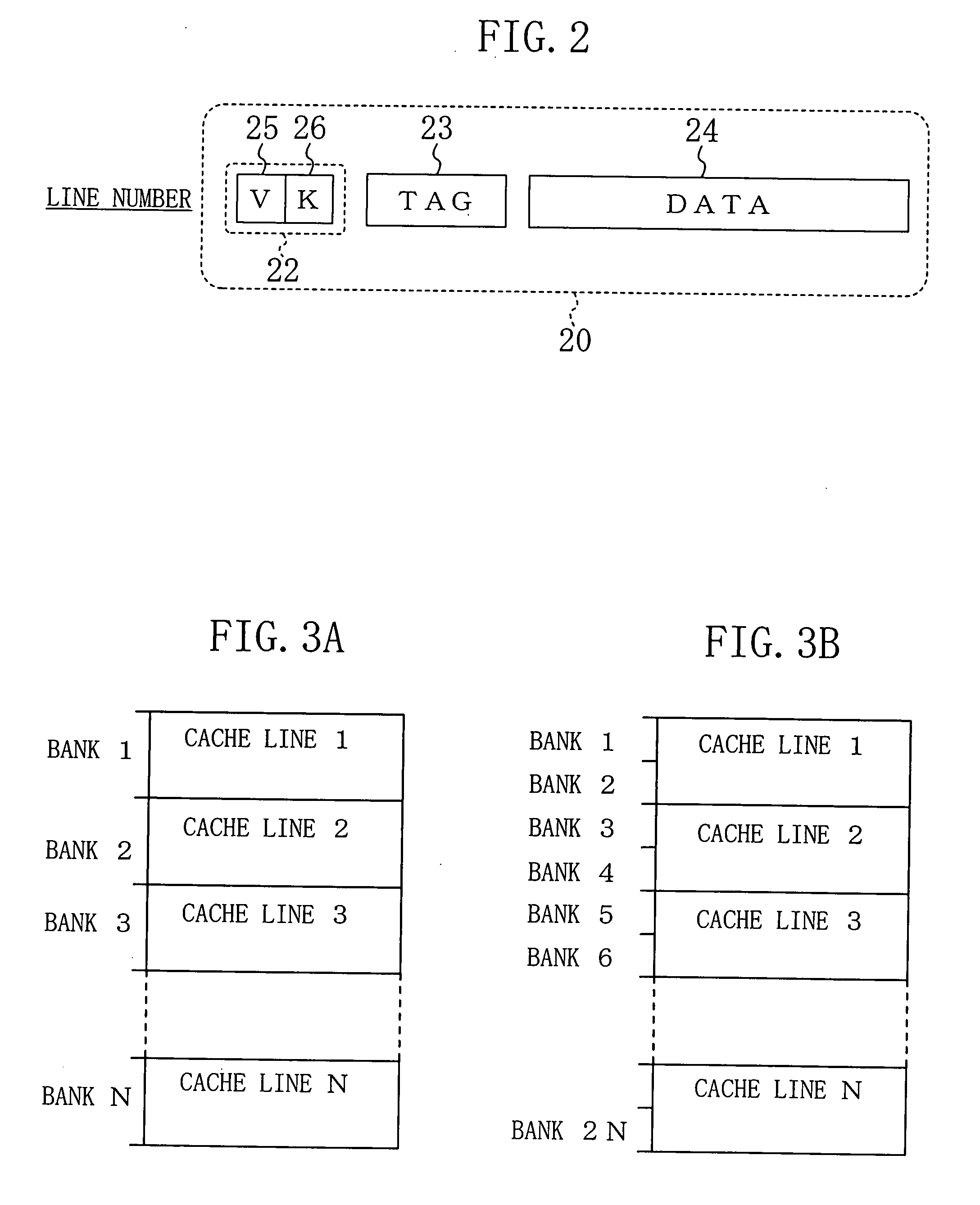
[0026]FIG. 2 is an explanatory view illustrating the configuration of a cache line 20 included in the cache memory 40 shown in FIG. 1. The cache line 20 includes an attribute section 22, a tag section 23, and a data section 24. The attribute section 22 includes a valid information section 25 and a line classification section 26. The valid information section 25 stores valid informati...

second embodiment

[0040]In a second embodiment, cache line copy function is added to the cache memory system of the first embodiment. A cache memory system according to the second embodiment is obtained by replacing the cache hit determination section 50 and the cache update section 60 in the cache memory system of the first embodiment shown in FIG. 1 with a cache hit determination section 150 and a cache update section 160, respectively.

[0041]FIG. 5A is an explanatory view indicating operation of the cache hit determination section 150 and operation of the cache update section 160 according to the second embodiment. FIG. 5B is an explanatory view indicating cache line determination according to the second embodiment.

[0042]In the following description, it is assumed that the cache memory 40 in FIG. 1 is a fully-associative cache, and that all cache lines included in the cache memory 40 are subjected to cache hit determination.

[0043]The cache hit determination section 150 includes a selector 152, a de...


PUM


Abstract

A cache memory system includes: a plurality of cache lines, each including a data section for storing data of main memory and a line classification section for storing identification information that indicates whether the data stored in the data section is for instruction processing or for data processing; a cache hit determination section for determining whether or not there is a cache hit by using the identification information stored in each of the cache lines; and a cache update section for updating one of the cache lines that has to be updated, according to result of the determination.

Description

CROSS-REFERENCE TO RELATED APPLICATION[0001]This application claims priority under 35 U.S.C. §119 on Patent Application No. 2006-177798 filed in Japan on Jun. 28, 2006, the entire contents of which are hereby incorporated by reference.BACKGROUND OF THE INVENTION[0002]The present invention relates to memory devices, and more particularly relates to a cache memory system which is used to reduce accesses to main memory.[0003]In recent years, cache memory systems have been widely used to enhance the processing speed of microcomputers. A cache memory system is a mechanism in which frequently-used data is stored in high-speed memory (cache memory) in or close to a CPU to reduce accesses to low-speed main memory and hence increase processing speed. Cache memory systems are broadly divided into the following two types of systems according to whether or not instruction memory and data memory are separated.[0004]FIG. 6 is a block diagram illustrating the configuration of a unified cache. The ...

Claims


Application Information

Patent Timeline
IPC IPC(8): G06F12/00
CPCG06F12/0846
Inventor SAKAMOTO, KAZUHIKO
Owner PANASONIC CORP
Why Eureka
Try Eureka