Heat sink

Inactive Publication Date: 2008-01-24
HON HAI PRECISION IND CO LTD +1
View PDF15 Cites 15 Cited by
  • Summary
  • Abstract
  • Description
  • Claims
  • Application Information

AI Technical Summary

Benefits of technology

[0007]According to a preferred embodiment of the present invention, a heat sink includes a fin unit having a plurality of fins parallel to each other. A flow channel is formed between each fin and its neighboring fin to allow an airflow to flow therethough. A protrusion is arranged on each of the fins and defines a through hole therein. The through hole communicates with two neighboring flow channels of the fin for the airflow flowing therethrough from one of the two neighboring flow channels to the other one of two neighboring flow channels of the fin. As a result the airflow can be r

Problems solved by technology

With the advance of large scale integrated circuit technology, high speed processors have become faster and faster, which causes the processors to generate more redundant heat.
However, this increases the weight and size of the heat sink, which conflicts with the requirement for light weight and compact construction.
This may avoid increasing the volume of heat sink 1, however, reducing the s

Method used


Image

  • Heat sink
  • Heat sink
  • Heat sink

Examples


Embodiment Construction

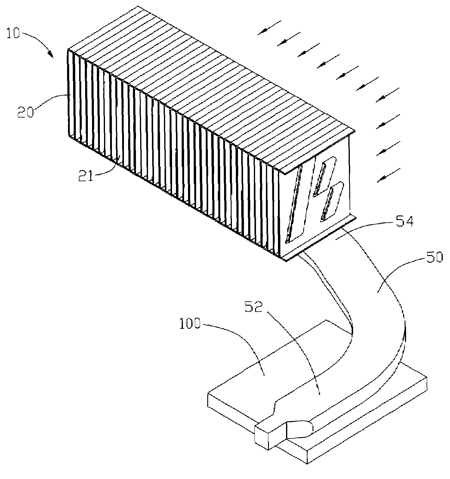
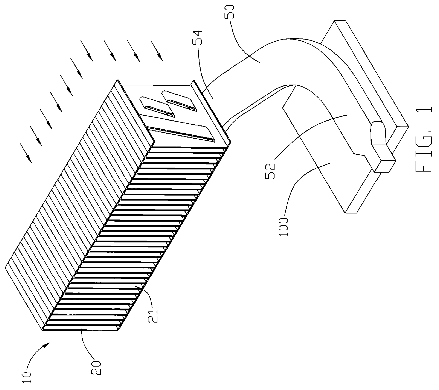
[0020]Referring to FIG. 1, a heat sink includes a fin unit 10, a heat pipe 50 being thermally attached a heat-generating electronic device, for example, a CPU 100 (central processing unit), to absorb heat therefrom and transfer the heat to the fin unit 10, and a cooling fan (not shown) arranged at a side of the fin unit 10 for generating airflow over the fin unit 10 as indicated by arrows.

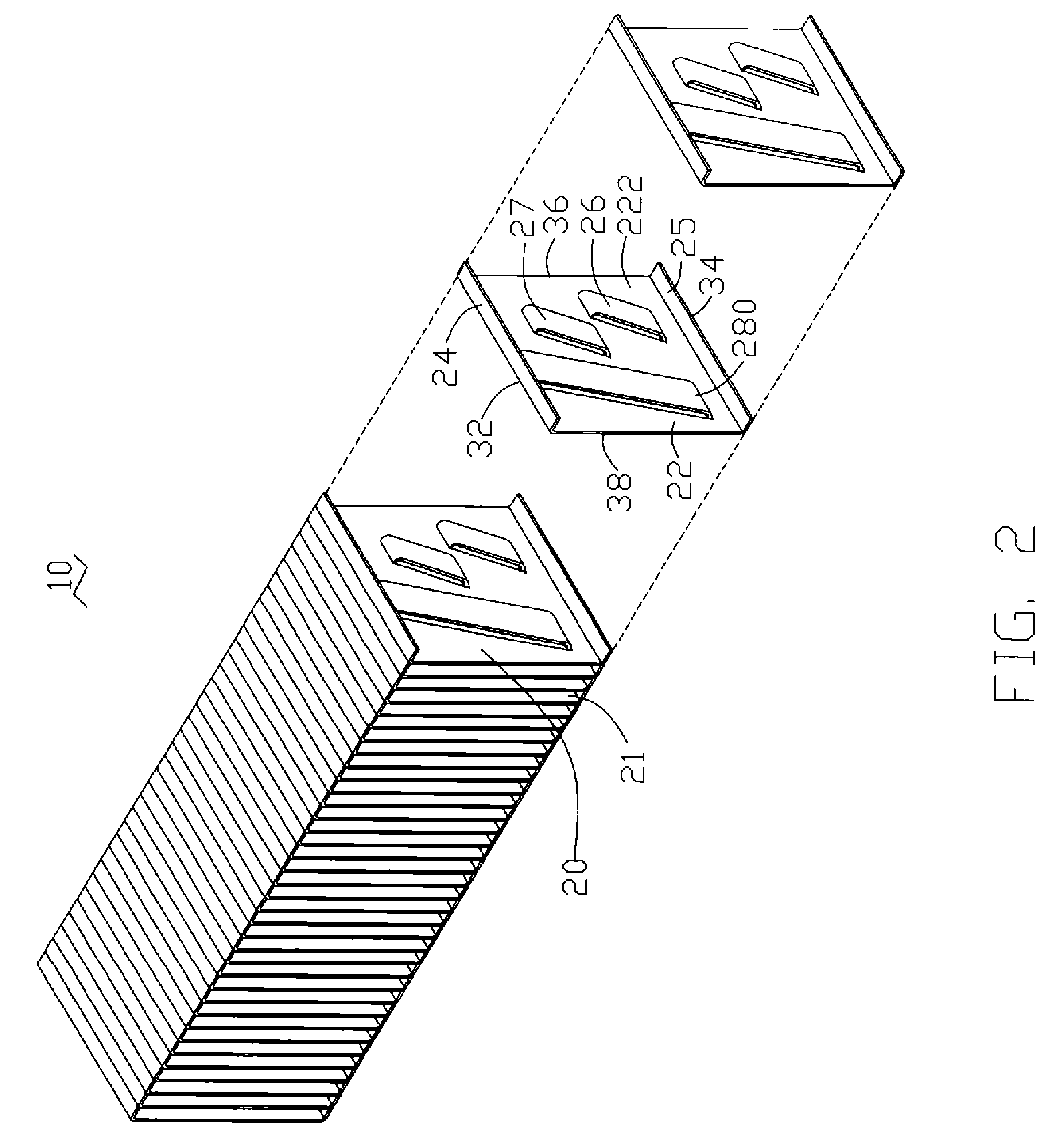
[0021]Referring to FIGS. 2-3, the fin unit 10 comprises a plurality of stacked fins 20 parallel to each other. A flow channel 21 is formed between each two neighboring fins 20 to channel the airflow. Each fin 20 has a square-shaped main body 22 which includes top and bottom edges 32, 34 extending along the latitudinal direction as the flowing direction of the airflow, and left and right edges 38, 36 extending along the longitudinal direction. Top and bottom hems 24, 25 bend from the top and bottom edges 32, 34 of the main body 22, respectively. Distal edges of the hems 24, 25 of each fin 20 contact...


PUM


Abstract

A heat sink includes a fin unit (10) having a plurality of fins (20) parallel to each other. A flow channel (21) is formed between any of two neighboring fins for an airflow flowing therethough. Three protrusions (26, 27, 28) are arranged on each of the fins and each define a through hole (42) therein. The through hole communicates with two neighboring flow channels of the fin for the airflow flowing therethrough from one of the two neighboring flow channels to the other one of two neighboring flow channels of the fin.

Description

FIELD OF THE INVENTION[0001]he present invention relates generally to a heat sink, and in particular to a heat sink with improved fin structure for achieving a high heat-dissipation efficiency.DESCRIPTION OF RELATED ART[0002]With the advance of large scale integrated circuit technology, high speed processors have become faster and faster, which causes the processors to generate more redundant heat. Redundant heat which is not quickly removed will have tremendous influence on the system security and performance. Usually, people install a heat sink on the central processor to assist its heat dissipation, whilst also installing a fan on the heat sink, to provide a forced airflow to increase heat dissipation.[0003]FIG. 10 shows a heat sink 1 in accordance with related art. The heat sink 1 comprises a fin unit 2, a heat pipe 4 extending through the fin unit 2, and a cooling fan (not shown) arranged at a side of the fin unit 2 so as to generate an airflow flowing through the fin unit 2. T...

Claims


Application Information

Patent Timeline
IPC IPC(8): H05K7/20
CPCH01L23/3672H01L23/427H01L2924/0002H01L2924/00
Inventor LI, ZHI-JIANHWANG, CHING-BAI
Owner HON HAI PRECISION IND CO LTD
Why Eureka
Try Eureka