Supercharge Your Innovation With Domain-Expert AI Agents!

Thin-film disposition apparatus

a technology of thin film and dissolution apparatus, which is applied in the field of thin film dissolution apparatus and chemical vapor deposition (cvd) apparatus, can solve the problem of not being able to provide an adequate supply of radicals into the film deposition process space, and achieve the effect of affecting performan

Inactive Publication Date: 2008-01-24
CANON ANELVA CORP
View PDF21 Cites 2 Cited by
  • Summary
  • Abstract
  • Description
  • Claims
  • Application Information

AI Technical Summary

Benefits of technology

This configuration enhances film deposition performance by maintaining radical purity and preventing precursor gas diffusion back into the plasma discharge space, resulting in improved film deposition rate and uniformity.

Problems solved by technology

The products of this reaction can lead to the generation of particles, and this has led to problems in that it becomes impossible to provide an adequate supply of radicals into the film deposition process space.

Method used


Image

  • Thin-film disposition apparatus
  • Thin-film disposition apparatus
  • Thin-film disposition apparatus

Examples


Embodiment Construction

[0035] Preferred embodiments of the present invention are described below with reference to the attached figures.

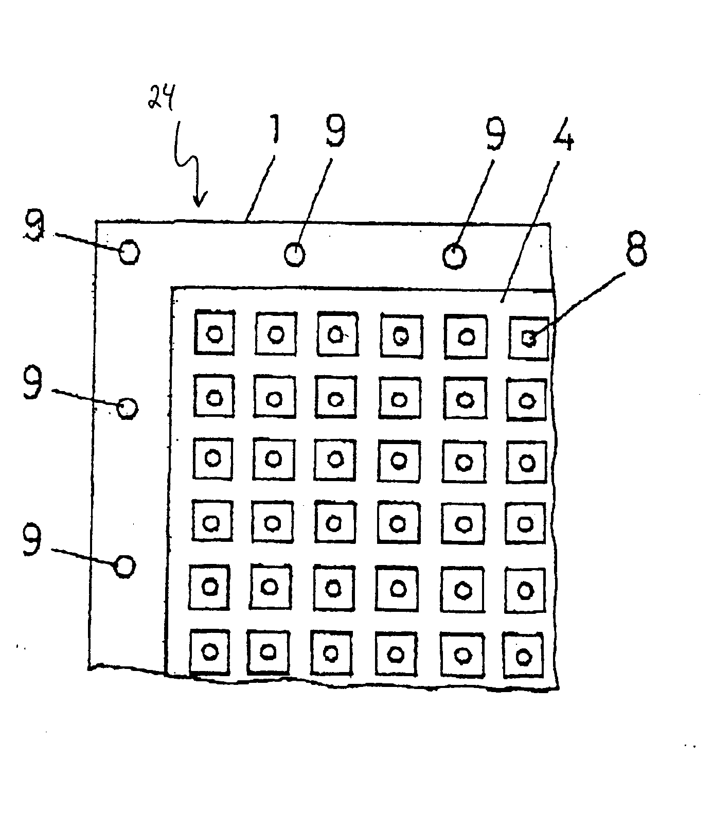
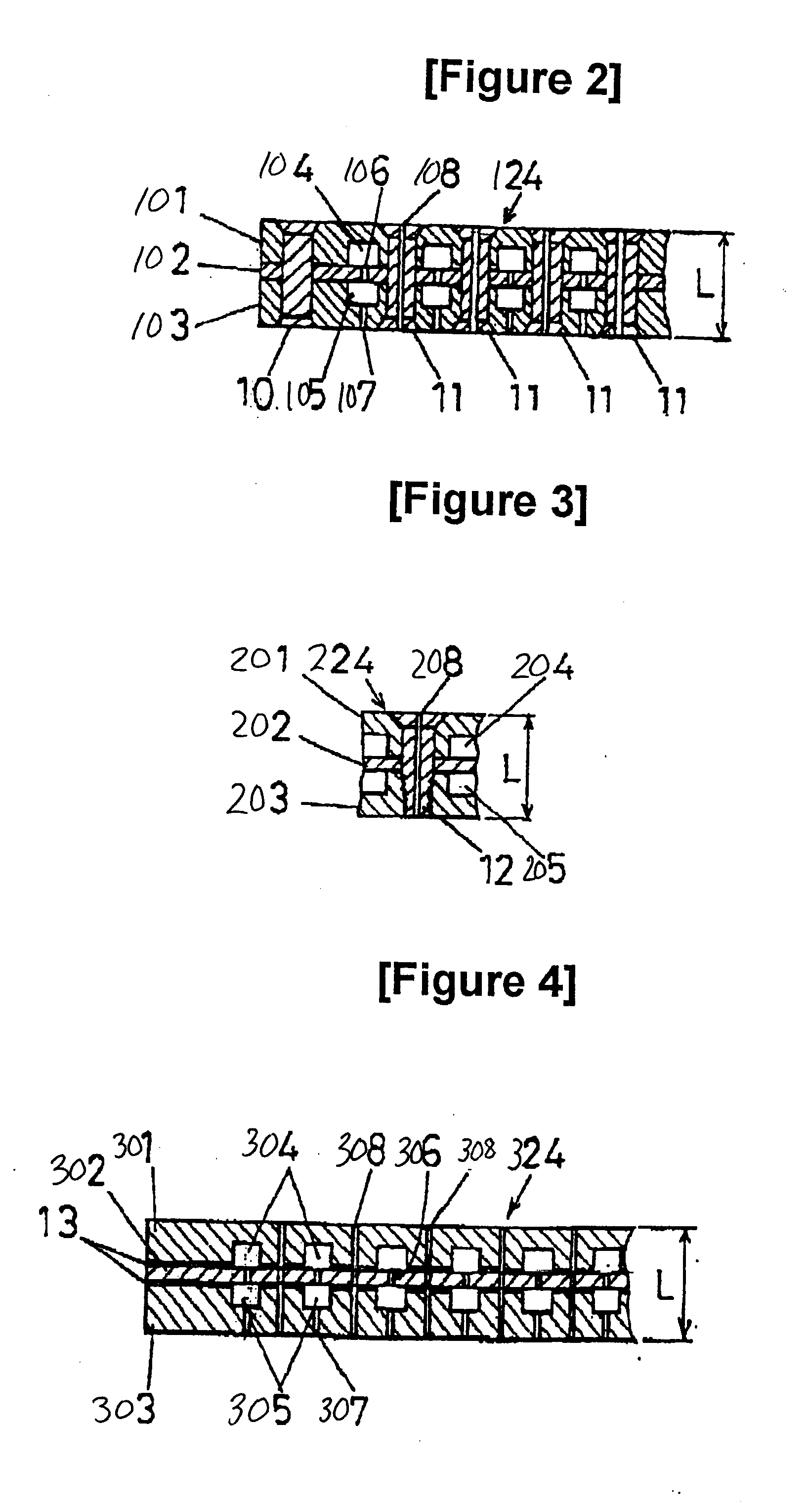
[0036]FIG. 2 is a cross-sectional view of a preferred embodiment of a dividing plate 124, which divides the vacuum reaction chamber of a thin-film deposition apparatus according to this invention (an example of which is shown in FIG. 5) into a plasma discharge space 25 and a film deposition space 26.

[0037] Dividing plate 124 is formed by fixing together a plurality of laminated plates (upper plate 101, intermediate diffusion plate 102, and gas discharge plate 103 on the film deposition side) by securely bonding them over the entire area of their interfacial surfaces or a large portion thereof (i.e., between upper plate 101 and intermediate diffusion plate 102, and between intermediate diffusion plate 102 and gas discharge plate 103 on the film deposition side) with a plurality of metal fixings, in this case by caulking with rivets 10,11. As used herein, the term interfa...


PUM

PropertyMeasurementUnit
temperatureaaaaaaaaaa
frequencyaaaaaaaaaa
temperatureaaaaaaaaaa

Abstract

A dividing plate for a thin-film deposition apparatus divides the interior of the vacuum reaction chamber into a plasma discharge space and a film deposition process space, by fixing or connecting a plurality of laminated plates together by securely bonding them over the entire area of their interfacial surfaces, or a large portion thereof.

Description

CROSS-REFERENCE TO RELATED APPLICATIONS [0001] This application is a continuation of U.S. Ser. No. 09 / 862,458, filed on May 23, 2007, and claims priority of Japanese Patent Application No. 2000-188667, filed in Japan on Jun. 23, 2000, the entire contents of which are both hereby incorporated herein by reference.BACKGROUND OF THE INVENTION [0002] 1. Field of the Invention [0003] The present invention relates to a plasma apparatus, and in particular, it relates to a chemical vapor deposition (CVD) apparatus suitable for depositing films on large-scale flat panel substrates. [0004] 2. Description of Related Art [0005] Known methods for the production of large-scale liquid crystal displays include methods that use high-temperature polysilicon TFTs (thin film transistors) and methods that use low-temperature TFTs. In liquid crystal display production methods that use low-temperature polysilicon TFTs, there is no need to use expensive substrates such as quartz because all the processes ca...

Claims


Application Information

Patent Timeline
Patent Type & Authority Applications(United States)
IPC IPC(8): C23C16/54C23C16/00C23C16/44H01L21/205C23C16/452C23C16/455H01J37/32
CPCC23C16/452H01J37/32623C23C16/45574C23C16/45565C23C16/50
Inventor TANAKA, MASAHIKOIKEMOTO, MANABUYOKOGAWA, NAOAKI
Owner CANON ANELVA CORP
Features
  • R&D
  • Intellectual Property
  • Life Sciences
  • Materials
  • Tech Scout
  • Unparalleled Data Quality
  • Higher Quality Content
  • 60% Fewer Hallucinations
Learn More