Aspirating labyrinth seal

Inactive Publication Date: 2008-01-24
GENERAL ELECTRIC CO
View PDF14 Cites 41 Cited by
  • Summary
  • Abstract
  • Description
  • Claims
  • Application Information

AI Technical Summary

Benefits of technology

[0006]The present invention provides a face seal with low leakage and high durability. The clearance between the seal elements is controlled so that the seal teeth will not rub against the seal rotor. This offers efficient

Problems solved by technology

Due to the initial gaps, and due to contact of the seals with adjacent surfac

Method used


Image

  • Aspirating labyrinth seal
  • Aspirating labyrinth seal
  • Aspirating labyrinth seal

Examples


Embodiment Construction

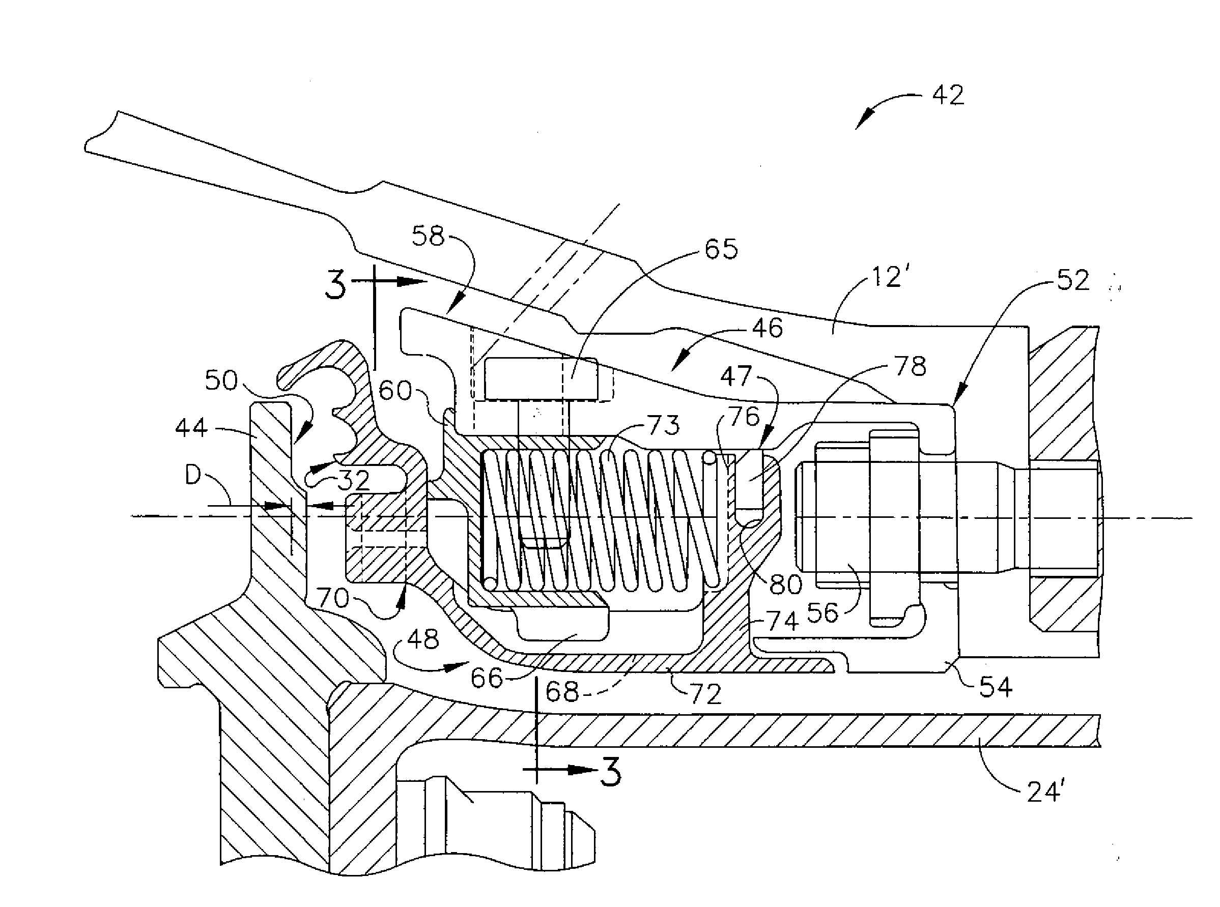
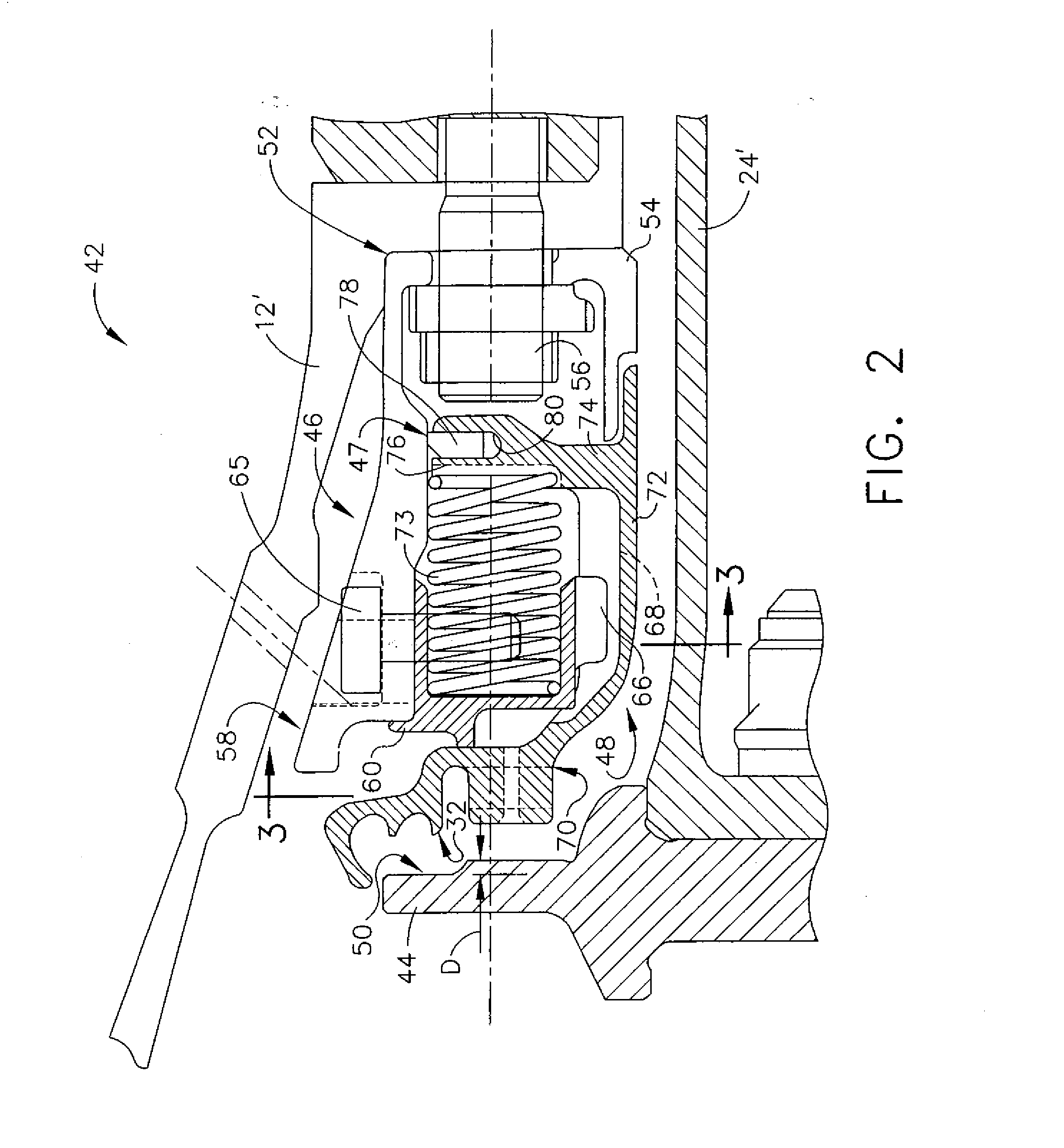
[0017]Referring to the drawings wherein identical reference numerals denote the same elements throughout the various views, FIGS. 2 and 3 show an exemplary seal assembly 42 which seals leakage between an area of relatively high pressure P(high) and an area of relatively low pressure P(low). In this particular example, the seal assembly 42 takes the place of a compressor discharge pressure (CDP) seal as described above and is disposed between a core shaft 24′ and a diffuser casing 12′, however it is to be understood that the features of the seal assembly 42 may be used in any application where a face seal is required. The basic components of the seal assembly 42 can include a rotor 44, a stationary seal support 46, and a seal body 48 (sometimes referred to as a “slider”), all disposed about a longitudinal axis of the engine. The rotor 44 is generally disk-shaped and defines a first axially facing primary seal surface 50.

[0018]The seal support 46 is a nonrotating, axially-extending co...


PUM


Abstract

A seal body includes an annular, axially extending portion; a radially extending portion defining a primary seating surface, and cooperating with the axially extending portion to define a generally L-shaped cross section; and at least one annular axially-extending seal tooth.

Description

BACKGROUND OF THE INVENTION[0001]The present invention relates generally to face seals for rotating machinery, and more particularly to aspirating or gas-balanced face seals.[0002]Face seals are used to minimize leakage through a gap between two components, where such leakage is from a higher pressure area to a lower pressure area. Such seals have been used in rotating machinery, for example steam turbines and gas turbines.[0003]In gas turbines, face seals are used between static hardware, between rotor and stator components, and may be used between different rotating components. The gaps or leakage paths between these different components must be sealed, and the seals applied need to be able to compensate for variations in the gaps due to differential thermal and mechanical component growths during the machine operating cycle.[0004]The variable gap to be sealed is commonly accommodated by either providing a compliant contact that is maintained between the components, for example us...

Claims


Application Information

Patent Timeline
IPC IPC(8): F16J15/40
CPCF01D11/02F02C7/28F16J15/342F05D2260/30F05D2250/41F05D2250/70F05D2260/52
Inventor HERRON, WILLIAM L.ALBERS, JOSEPH C.GLYNN, CHRISTOPHER C.CRUDGINGTON, PETER
Owner GENERAL ELECTRIC CO
Why Eureka
Try Eureka